|
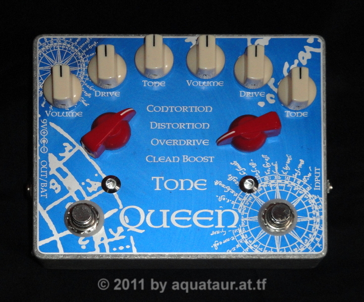
The Tone
Queen More Eclectic Than A King... A Queen! last update: May 14, 2011 Copyright
2010-25
by H.
Gragger. All Rights Reserved. All information
provided herein is
destined for educational and D.I.Y. purposes only.
Commercial re-sale,
distribution or usage of artwork without explicit
written permission of
the author is strictly prohibited.The original
units with
their
associated trade-names are subject to the
copyright
of the individual copyright owner. The Author is
by no means affiliated
with any of those companies. References to trade
names are made for
educational purposes only.By reading the
information provided here you
agree to the Terms
of
Use. The working language
is kept in English as an aid. Read here
why.
|
|||||||||
| MAIN PAGE>MUSIC
STUFF>TONE QUEEN Index Tube Tone
Without
Tubes?
Back To
IndexThe rant about tube tone without tubes goes on. After building all those well reputed dirt boxes with a charm of their own I decided to tackle tube tone this time. A few commercial boxes have been reverse engineered for the schematics to behold thanks to the good work of others. The King of Tone had earned the best reviews for what I was looking for, so I built one (or, to be more precise, Madbean´s Aristocrat, which I have no doubt is a faithful clone of the KoT), evaluated its features and eliminated some of its subjective flaws. The resulting pedal has a lot of the KoT, but it has more. Amongst others, some extension has been made towards a Fulltone OCD, so it has become at least three entities in one house. It has become more eclectic than a King of Tone, it is a Tone Queen. Back To Index
A Closer Look At The KoT-clones´s Architecture And Modes
The So-Called Clean Boost On
the input the KoT-clone has a network for biasing
the opa at
half-supply,
this yields an input impedance of 500kOhms - not
overwhelming, but
sufficient.
Far less good is the fact that there is no
mechanism to stop HF
intrusion. This may lead to slew
rate
problems as mentioned in another article of
mine.
Although we are talking about frequencies beyond
the audio band,
RF may be heterodyned down into the audio band. A
simple RC that
tailors
the HF response will do away with that.
Back To
IndexThe gain of the first stage (disregarding the frequency shelving caps for the moment) will settle around 10 or so, dependent if you use the stock 100k drive pot or the 250k. On my Strat I observed some 500mVp-p signal amplitude upon hard picking; more is to be expected from humbuckers. Amplified this yields some 5Vp-p, which is about the maximum one would tolerate for a high fidelity circuit with a 9V rail without inviting substantial signal degradation. The subsequent amplifier stage has a basic gain of 220/10k equalling 22. In "clean boost" mode with drive fully wound up, this will invariably lead to substantial op-amp clipping. Although the guitar´s signal rapidly decays from a peak amplitude to some level, the peak clipping is readily noticeable by the ear. This is where individual op-amps will really show their different reaction and how they "sound". In general I observed, that most opa´s do not clip until the signal is very close to ground and about 1V below supply. The very unfortunate thing about the "clean boost" mode is that the stock user does not know about technicalities. He or she would think that everything is well and gain is low, since the overall gain is unity (what goes in comes out) and happily run the KoT-clone with high drive settings. In truth the internal gain due to a high drive pot setting might be excessive, it only appears low due to a low volume pot setting. This is normal practice in valve amps, but there the supply overhead is comparably enormous. The often hailed "clean boost" mode of the KoT-clone therefore is a rather inferior mode due to the risk of op-amp clipping. If somebody were determined to use the KoT-clone for clean boost I recommend to wind the volume pot up fully and control the overall volume with the drive pot - it is a clean boost at last and no control should be preferred. As soon as distortion sets in audibly, one should stop. If huge clean boost reserve was desired, one would resort to some other device like the Klon Centaur that has at least double the supply voltage available (Note: I have not tried the Klon yet so see how good it performs in this respect). As mentioned before, the first stage of a stock KoT-clone with a 100k drive pot operates within fairly save voltage margins, but using a 250k for additional boost may drive already the first stage into clipping, regardless of what follows. This not only worsens the situation for a clean boost, but also for all other modes. It is left to the judgement of the individual user whether a fatter sound is worth the cost of some pre-distortion. Not addressed yet has been the fact, that the "clean boost" is by no means neutral in tone as the name would suggest. Although for the test candidate the suggested 47nF input caps were used for extended bass range, the "clean boost" still has more of a treble boost. This stems from the frequency shelving caps in the feedback section of ICxA, and if true clean boost were desired, those caps would need to be fiddled with. Back To Index Overdrive Mode Let´s look at the "overdrive" mode next. This uses basically a diode pair in the feedback loop. The loop´s basic gain of 22 is modified as soon as the diode ladder begins to conduct. This will be at a higher voltage than the diode threshold would suggest due to the added compliance. As we have seen in my diode mojo article, a diode section pair section with compliance can be a substantial approach to tube tone, and indeed the KoT-clones´s overdrive mode does this very well. It sounds very natural, unprocessed and tubey to my ears. Similar statements have been issued by the band members. Jack Orman has made a side-step towards this, calling it "warp control", a term that in my eyes contributed more to distraction than to clarity. Basically the article is correct, but in my eyes is does not give as much insight as Kevin O´Connor does in his books. The compliance resistor seems well chosen because any lower resistor would lead to bigger compression, any bigger resistor would eventually end in no bounding at all. The diode ladder now behaves mostly like a tube diode would behave, tubey signal shaping and pleasant sound. Thumbs up! A side effect of the bounding circuit is that even if driven heavily the output voltage would never approach the rails. The earlier mentioned fact that the opa might encounter slew rate limiting also appears less critical due to the less radical change thanks to the compliance resistor. Output signal is fairly substantial due to the increased voltage span. It is well known that the device following a more crude distortion box will mask its predecessor´s harshness. This is most certainly true for the overdrive mode of the KoT clone. It sounds as if the dirtbox were played into a smouldering tube stack. Back To Index Distortion Mode The third option, "distortion", is a classical shunt diode clipper, which exhibits zero bounding, worsened by the usage of low-capacitance diodes. Comparable circuits from other builders that use 1N400x diodes or similar have substantial internal capacitance values that help to tailor HF response by effectively creating capacitive compliance. The author does not have access to the original exotic diodes so no statement can be made on the sonic qualities thereof. [Not that there were any interest to acquire any...] Anyway, this topology fully limits the signal whatever amplitude it had before, to the diode threshold, thus creating heavy compression. The drive control does not do much to volume, it just changes the texture of the distorted sound. Also the volume control´s range is limited in this mode. There is not much variation on the output. One additional drawback of this topology is that similar to the clean boost mode, the signal leaving the second opa stage may long be clipped at the rails, particularly with the "hot" drive pot, before it ever hits the shunt diodes. Whether this is appreciable or not, is left to the imagination of the kind reader. Other circuits do this trick better. Using both modes together (both DIP switches on) is far superior, because the signal can never be clipped in any unexpected (or unwanted) way. It is bound by the feedback diodes to save levels. Moreover, it is often said that good distortion comes from distributed distortion mechanisms. Back To Index The Mid-Voltage Flaw As common for a single supply op-amp circuit, an arbitrary mid-rail voltage has been derived for establishing a working point with maximum headroom. Rather uncommon is that the series shunt clipper is DC referenced to this mid-voltage rather than AC referenced to ground. This bears some resemblance to the tube screamer series, which may not be accidental. However, in this arrangement lurk some traps. Monitoring the mid-voltage I noticed, that this drops considerably (more than a Volt) when the series shunt diodes are starting to conduct, because current is drawn from the filter capacitor there. This is particularly bad, since that further decreases the already small headroom. I also noticed that the mid-voltage is established through a 47k/47k network, which is not low impedance. Together with a 100µ electrolytic this gives quite a slow start up upon power turn-on. During this time one should not attempt to switch channels, since the DC shifts involved will invariably cause audible pops. Back To Index Noise With two LM833´s in place, both channels on give quite high noise. Big enough, that my noise gate does not shut down any more. Although the sound is not bad, it is not dramatically different or better than a single channel at the cost of enormous gain and thus noise. Diode Subbing And Exploiting Nothing can be
said about
the sonic virtues of the original diodes used - I
just had no
comparison.
Back
To
IndexOn paper, the BA278 is a perfect replacement for the MA856 as shown in the comparison chart. Their performance in the circuit does leave nothing to be desired, so that was the end of the discussion. The other diodes of unknown type I salvaged from Japanese consumer electronics do not only exhibit a much lower threshold, but sound differently. They perform different compared to the BA278 in this position, so I left them there with some additional compliance to utilize the spare switch position. Note that I have given both half waves different compliance values, as there is some indication that tube stages clip half waves differently. This measure also brings up the bounding levels to similar voltages. 1N4148 are on the paper ideal replacements for the 1S1588 diodes, however they sound somewhat generic. Other circuits are known to make more out of such a shunt diode clipping section if hard clipping were desired. Maybe the 1S types really sound better. I tried MOSFETs (BS170 and with equally pleasing result, 2N7000 and BS250), and although their intrinsic diodes behave by no mean similar to the 1N4148 (which is a fast diode), they sound far far superior. I also spent some asymmetricity with an additional ge-diode, as I have seen it done on the Fulltone Fulldrive MOSFET edition and the OCD. The resulting circuit sounds killer, adds a gnarly tone to the already bound signal. Op-Amp Choice I tried a couple of the usual specimens, RC4558, LM833, NE5532, MC1458, which all sounded similar. Interestingly, against all expectation the much faster LF353 sounded inferior, lacked bass. I have no explanation to that. The 5532 I avoided due to its unusually high current consumption and its input diodes. I finally settled on the LM833 for no particular reason. The LM833 has noise figures superior to the NE5532 and most certainly all contestants mentioned here. Back To Index Level Equalization Issues Using the DIP switches (or rotary switches on the Tone Queen) to select a different mode invariably produces a volume step. Dialling in the
overdrive
tone produces a volume step up, whereas the
distortion mode means a step down due to strong
limiting and
compression compared to the "clean boost" mode
[N.B. this refers to the
Tone Queen´s
switching
circuitry. Magnitudes will be different on the
original KoT].
Since heavy compression practically just produces one output level regardless of the input dynamics, there is no easy way to equalize the volume for all options. But because this is no control that is activated during performance, but rather a preset, this is no harm and no further attempts were made to change the situation. Clean boost gain has been toned down as described in the next section. Switching from overdrive to clean boost will produce a lower signal dependent on the low but noticeable compression. Enabling both channels simultaneously normally produces a volume step, even if both channels on their own are set to unity gain subjectively. This stems from varying amounts of compression both channels have dependent on the distortion type setting. Compression fouls one´s sense for loudness because loud signals are made less loud and vice versa. In the extreme, all signals are made equally loud. So dependent on playing style and attack a volume setting may appear to have the same loudness as the bypass signal, while in other situations it appears different. Although the KoT clone has, compared to other units, low compression, chaining two channels yields a loudness step. Back To Index Interstage Equalization One more reason may be that usually the highs are accentuated by clipping circuits. Since the KoT-clone architecture favours high frequencies anyway, driving channel 2 (e.g. series shunt clipper) with channel 1 (e.g. diode bounding with compliance) will yield a treble overload of channel 2. The latter sounds way too trebly if daisy-chained, although the individual channels sound subjectively good. This can be fixed by turning the treble of channel 1 down with its associated tone control in daisy-chain mode, which incidentally also reduces volume. Unfortunately this is not very practical, since reverting to channel 1 alone results in an overly dull tone which requires tweaking the tone control. Remember, we are actually dealing with two indepedent pedals. You cannot just run one distortion pedal into the next without some equalization. This fact stresses the necessity of pre-distortion equalization. Every musician knows that distortion pedals produce more or less unwanted high frequency content that needs to be tamed - by using an equalizer of sort. Little understood is the fact that what comes out is just a product of what goes in plus the effect, so some pre-effect equalization might be in order. This is vital to smooth overdrive sound and has been discussed on FSB and on amptone. The issue has not been addressed in the KoT at all. Funnily, they offer a break jack as an dear option, kind of "send-return-loop", that would cater for just that. A circuit of strikingly similar architecture for example, the Really Smooth Overdrive, uses a second-order low-pass filter to remove harmonics before the distortion section, because that section will produce harmonics galore anyways. This yields a somewhat different compression pattern over frequency, although the signal does not appear to lack treble. Note that the above mentioned circuit uses compliance just as the KoT clone does. It does, however, not have a drive control. As a matter of fact, reportedly the stock drive control on the KoT hardly ever gets moved from the "full" position, so using the guitar´s volume control to back off distortion slightly appears fully justified. The "hot" version of the KoT, as mentioned, is prone to amplifier clipping in the first stage and should be avoided. KoT clone Synopsis Looking
back on all the hair-raising flaws I have detected
on stomp-boxes, I
wonder if any of
the musicians really look at what they buy. I
wonder even more,
if any of the engineers that re-vamp such a
circuit (because that is
what usually happens...), understand what
they are doing.
The
KoT clone certainly has its virtues. Its overdrive
mode is beautifully
sweet due to the resistive compliance (and
possibly choice of diodes),
although nothing new from a technical standpoint.
Interestingly, this
is seldomly seen in circuits playing in the same
league. If the KoT is
viewed as a once-preset box, this may justify its
purchase, letting
alone price and delay issues.
The
clean boost section is useless IMHO, it lacks bass
despite the
increased input capacitors and is prone to op-amp
clipping due to lack
of headroom.
The distortion section has leeway for improvement that has not been nearly exploited. The
concept of daisy-chaining two overdrives slightly
suffers from loudness
or
frequency imbalance (which is probably why the
special option with
"breakout jacks" is offered...) and has not been
carried to perfection
yet,
although the basic tone achieved after some
tweaking is good.
The advertised 1M input impedance is rather 500k, which is not too bad. They have overlooked that R1 and R2 are effectively in parallel for AC, since Vb is a low impedance rail. Still, bigger resistors would not hurt. Using the tone control always produces a volume drop towards bassier sounds, which requires simultaneous touching of the volume knob. This is a pain. Fortunately, some of those flaws are easy to eliminate and so we will do... Back To Index Building The
Queen
Back To
IndexThe clean boost section bears, as mentioned before, the danger of op-amp distortion in the second stage. This has been minimized by putting a 47k resistor in parallel to the 220k (R7/R21) feedback resistor, thus limiting its gain to about five. This approach still provides some output for a boost, while op-amp clipping is minimized. The question is, how much clean boost does one need? The treble-boost action of the clean boost section was left unaltered, since no real usage for the "clean" boost was in sight. Note: component designators refer to Madbean´s single sided layout for the Aristocrat. The added extras ultimately killed any notions of a small case, so the bigger case was chosen. This is fully justified taking into account, that the resulting pedal in fact functionally comprises at least three other pedals. The DIP switch sockets have been replaced by solder pins, the diodes by wire bridges. All tricky feedback and shunt diode configurations have thus been moved to an external small board that is mounted directly to the rotary switch and wired to the main board with four wires per side. Disregarding the extended possibilities this approach offers, a stock building is possible with this set-up too. It was decided that the "overdrive only" option was not incorporated in the queen due to the hazard of clipping in the second stage as mentioned earlier. The salvaged Japanese diodes (two green bands on a glass container) were used on the now free position 3, albeit with more (and individual) compliance due to their lower threshold. Position 4 is equivalent to both DIP switches on the stock build. Due to the diode bounding, there is hardly any op-amp clipping to be expected. Also, this will yield harder saturation due to pre-distortion. As mentioned earlier, MOSFETS have been chosen with some threshold-offset in form of a ge-diode, much as the OCD has it. The overdrive diodes BA278 are in action, but with a slightly increased compliance (series resistance)
Note: the switch assemblies for left and right are reverse in switching sense to allow for a mirror image layout. In retrospect, the Alpha switches I received from Musikding appear not very sturdy, time will tell how long they survive on a musical gadget. The mid-voltage flaw has been eliminated by adding a second capacitor on the high side, from mid-voltage to the supply just after the diode. By doing so, during clipping power is drawn from both rails and no deviation from the mid-value occurs. Also, the resistors R12 and R13 were reduced to 2x12k, which provides a faster start-up with no adverse affect otherwise. The diode D7 (on the power input has been replaced by a Shottky diode which dramatically reduces the unnecessary .7V drop from the battery supply with no adverse effect. I should not forget to mention, that the BA278´s I received were SMD. I failed to realize that the package they come in is only about 1.5 mm - too small for me old eyes. I had to make minute adapter boards to inflate them to a size that can be handled by a mere mortal. But it is worth it. I used carbon type resistors in all positions and mostly polyester film caps as available in my rumble box except for C2/C13, a 100 nF mica cap. I know from earlier projects that using these in the signal path can be crucial for taming unwanted HF. Royal Encounter - Long Time Experience  Letting the
Queen cool
over a few days, I played with her again. I know
that sonic impressions
are different on different days.
Interestingly, the volume / treble step between channel 1 or 2 and 1 + 2 does not appear too bad in retrospect, although it is present. Playing with fuzzes and dirt boxes into the queen yields some interesting tone changes. Although it contributes only a little overdrive, the Queen masks her predecessors tone to the benefit. This is reminiscent of a tube amp´s input. There is some demo sounds that try to demonstrate this. Unfortunately the recordings don´t reflect the whole capacity. The overdrive mode on its own is so beautifully dynamic and raunchy that it has a good chance of staying on all the time. Whoever designed the KoT resp. Bluesbreaker circuit, full respect to him or her. There are a few inconspicuous yet crafty features to be found in it. Referencing all nodes within the circuit that normally go to ground to the arbitrary mid-voltage instead (such as filter caps or pots) eliminates the need for a lot of interstage capacitors. This not only brings the price down, which would not be too consequential for the hobbyist, but also eliminates all discussion on capacitor types and the musicality thereof. Output coupling caps are made (half at least) non-polarized. This similarity to the tube screamer circuit might not be purely accidental, which may account for a similar acceptance. The original op-amp, the JRC4580, is the common flavour type and can readily be replaced by one of the popular types. However, since the overall circuit gain can be high enough to cause amplifier clipping, all measures to minimize unwanted distortion are welcome. The first half of the opa is particularly prone to harsh-sounding clipping, so I was in the verge of exchanging the front end with a discrete MOSFET gain stage when I remembered Bi-MOS opa´s like the ICL7621DCPAZ or the similar CA3260 that are drop-in replacements. Those devices are particularly suited for single rail supplies and can be driven to levels approaching the rails to within millivolts in contrast to the 1-2V drops of the beforementioned devices. Moreover, any clipping, which will be inevitable at some point, will happen graceful - no different from the MOSFET pair we employed for the very purpose of clipping. High drive settings on the clean boost thus sound much clearer. Incidentally, current consumption is one tenth of the other opa´s. Note however, that those devices cannot be used with higher supply voltages in case a voltage doubler were planned, but such a measure would take the reason for the single rail opa ad absurdum anyways. The CA3260 has a much higher slew rate and gain capability and might be the preferable device. However, A/B comparing the ICL7621 on one channel and the previous LM833 on the other I could not detect any audible difference in the overdrive modes on moderate settings but indeed there is a noticeable improvement in clarity on the clean boost setting at full boost. Both devices have a push-pull output stage, so no adverse effect on output drive capability is to be suspected. Neither was one noticed. One additional step to preserve headroom is to use a Shottky diode in series with the supply rather than a standard silicon diode. Another subjective improvement I made is to double the interstage coupling cap (indeed the only one around) for extended bass range. The KoT is pretty trebly. Back To Index Sound Samples The
subsequent
recordings have been done using the
following setup (in sequence):
(Names may be
copyrighted by the
associated copyright holder)
Update History
MAIN PAGE>MUSIC STUFF>TONE QUEEN |
|||||||||
| MAIN PAGE
| MUSIC STUFF | IMPRESSUM (c) 2010-25 AQUATAUR Musik & Elektronik |
