|
The
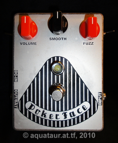
Poker Face - a
no-compromise fuzz face A fuzz face implementation with vintage sound but modern attributes Part 2: practical implementation last update: May 14, 2011 Copyright
2009-25
by H.
Gragger. All Rights Reserved. All information
provided herein is
destined for educational and D.I.Y. purposes only.
Commercial re-sale,
distribution or usage of artwork without explicit
written permission of
the author is strictly prohibited.The original
units with
their
associated trade-names are subject to the
copyright
of the individual copyright owner. The Author is
by no means affiliated
with any of those companies. References to trade
names are made for
educational purposes only. By reading the
information provided here you
agree to the Terms
of
Use. . The working language
is kept in English as an aid. Read here
why.
|
||||||||||||||||||
| MAIN PAGE>MUSIC
STUFF>POKER
FACE PART2 MAIN PAGE>MUSIC STUFF>POKER FACE PART1 Index
The reasons behind the
implementation of the subcircuits described here
are explained in
detail in part 1 of this series. I suggest you
read part 1 before
proceeding.
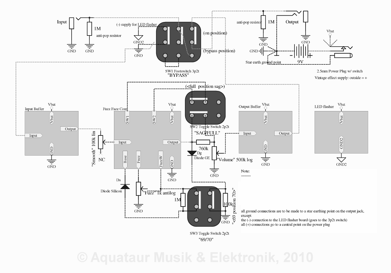
Circuit overview (block diagram)
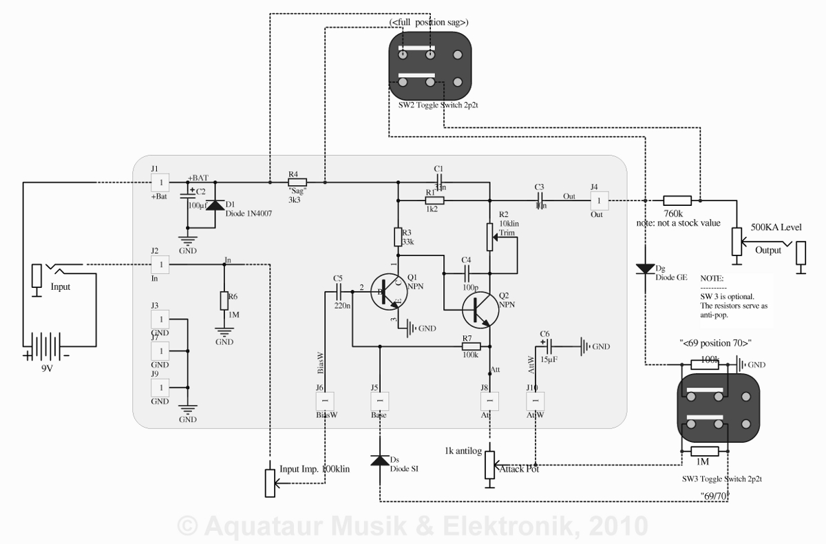
Back To Index The heart behind the Poker Face - the fuzz face core I was debating awhile
whether to
depict my rendering of a fuzz face or not to not
infringe
anybody´s
copyright. (If someone feels that I do so, let me
know and I will
remove the circuit). I came to the conclusion that
the fuzz face
circuit is so ubiquitous, with little amendments
here and there, that
there is no danger.
As mentioned
earlier, the
design
builds on an earlier design from Fuzzcentral,
namely the Axis
Face
Silicon. A few subtle changes compared to
the basic
circuit have
been implemented there, please read this page for
the details.
In the following I show my own implementation with the changes I have made since I am referring to them. No more has to be said otherwise.
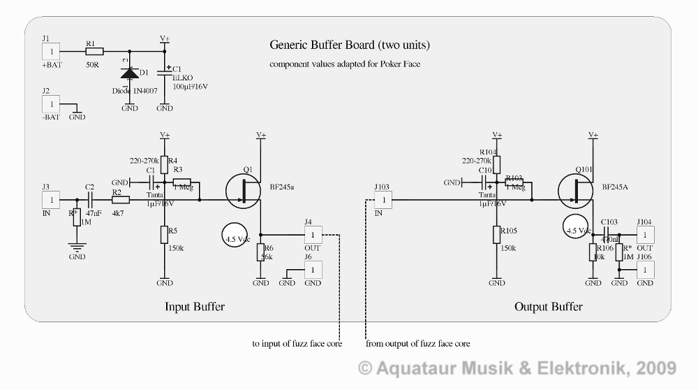
One thing seems imperative, C4 needs to be of mica type. At the time of assembly all I had was a ceramic capacitor and I thought it would not make any difference. Philip Bryant specifies a mica cap, but does not particularly stress its importance. I later found a passage in one of his forum threads where he particularly points out the necessity thereof. Indeed the circuit sounds even smoother with a mica cap. Back To Index Practical implementation of the output buffer
Let´s start
with the easy
one
– the output buffer. All we need to
do is to separate the volume pot on the output
from subsequent
circuitry that is liable to load the output´s weak
drive. A
simple j-fet buffer was chosen for low noise and
low current. This is a
standard buffer with the slight
modification of an additional resistor that pulls
the working point up
to achieve a better output swing capability. The
Resistors R4 / R104
have
been
selected for a 4.5 V quiescent voltage at the
source. Normally such a
buffer has a capacitor on the input, but since the
poker face´s
core circuit (basically a axis face silicon) is
equipped with an output
capacitor anyway, it was omitted. Note the extra
tantalum decoupling
cap
on the above mentioned resistors, which proved to
be necessary to stop
switching noise from the optical status indicator
LED circuit leaking
through into this medium-impedance circuit (see
later).
Although the buffer´s output has a source resistor R5 / R105 to set a certain current (chosen for low noise and low current demand) its drive impedance is dominated by transconductance, which is effectively in parallel. The resulting impedance is some 100 Ohms for a BF245A – low enough to drive even the longest cables. If somebody felt that buffering the output of some (existing) FF device would render tone unnaturally sharp, look at the solutions outlined later. Back To Index Practical implementation of the input buffer The input
buffer is
somewhat more
demanding, in so far we need a pretty
high output impedance. The technician calls this a
current output,
which is an uncommon requirement for a buffer
device. I was hunting
through my circuit cellar for such a circuit and
did not find much.
Most circuits are voltage output, the rest too
complicated. Anyway, a
current output can be
mimicked by a voltage output plus a sufficiently
large series resistor,
provided the voltage swing capability of the
driving circuit is large
enough. This
is in effect achieved by the variable series input
resistance as
suggested by Fulder.
Back
To
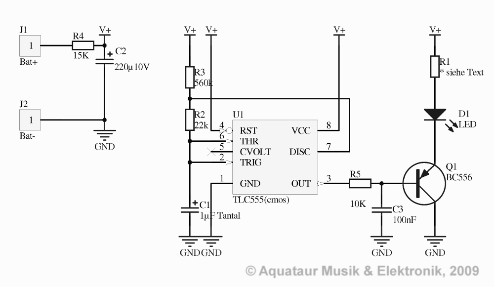
IndexI tried a quasi class-A circuit, meaning that the resistor from source to ground was formed by the fuzz face´s input impedance of some kOhms, but this did not work. The circuit seems to need some DC path, and with a resistor in the order of a guitar´s average drive impedance (I tried 56k) it works. The question arose, if such a low drive to the BF245A does contribute to noise, but the noise coming from the fuzz face itself seems prevalent despite the fact that the j-fet is not operating on a drain current of lowest noise (albeit lowest quiescent current). The resulting drive impedance, however, does not significantly vary with the magnitude of the source resistor in spite of the big value chosen, because both are effectively in parallel. I will spare you of the theory. I tried a j-fet with much lower transconductance, or higher output impedance so to speak, namely a J201, but this refused to work in this environment. Some more investigation on the subject seemed in order, but since it works anyway, I could not be bothered. Again, the output capacitor was omitted for reasons explained before. Remember, series capacitors result in a decreased total capacitance, and this is undesired. Thus the frequency dominating elements adhere to the fuzz face core. The input has a series resistance of 4.7k which, together with the j-fet´s input capacitance stops radio frequent interference right from the start, into the bargain. Note the added 1Meg capacitor bleed resistors on both input and output that aid to render switching noise inaudible. Optical status indicator LED – a refined LED flasher Standard
LEDs draw around 20 mA of current, low current
LED´s one tenth of
that.
This is still in the magnitude of the current
consumption of the rest
of the device, if not bigger. A status
indicator is
definitely
desirable, but such current demand is clearly out
of discussion,
which is
why some
designers abandoned an optical
indicator entirely.
Many people suggest LED flashers. They blink with a frequency in the range of some cycles per second for the user to appreciate, with a fractional “on-time”, which drops the average current consumption to negligible values.
Unfortunately
this
circuit is prone
to inject switching noise (ticking) into the audio
path, which
is why design engineers do not frequently make use
of it. And indeed
it took me some scratching of head to remove this
problem.
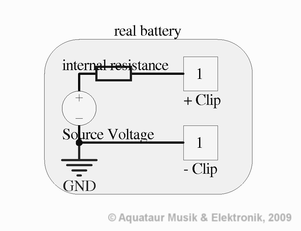
I started with a low-current LED and a 1.2k resistor for R1 which yielded a current draw of 2mA during the “on”-time. Reducing the LED current does clearly reduce ticking noise, so I found an ultra bright white LED (those with the blueish tint) from a defunct headlamp, which works a treat. Together with a 4.7k resistor the average current demand over time will be negligible, while brightness is still blinding. An even bigger resistor might be used without degrading performance. This improved clicking a little bit. As further measures I slowed turn-on and turn-off time by inserting an RC between the 555 and the transistor. This helped a lot, may the result be attributed to slower rise and decay times or reduced IC drive current. As already mentioned, the medium-impedance paths that set the working voltage on the buffers were bypassed with tantalum caps. This worked a little too. I looked at the supplies with a oscilloscope, but these were clean and thus appeared sufficiently bypassed. Additional IC decoupling did not help at all. After all those measures some residual 2 Hz ticking noise, although vastly reduced in magnitude, was still present. In the process of tinkering I noticed, that dislocating the flasher board (remember, on the prototype all sub-units were assembled on individual boards) stopped the noise, which lead to the suspicion that some static coupling into high impedance circuits was the cause for the annoyance. I finally managed to suppress the remaining noise successfully by wrapping the whole flasher circuit first in insulating tape, then in aluminium foil that is grounded by being in contact with the grounded case. The switching ticks are inaudible even with the input left open (some 500k input impedance) and all controls maxed. I thought I could be very pleased with the result. If somebody wished to implement all sub-circuits on one single board, s/he might be in trouble for exactly that reason. It is quite common that prototypes with bits and pieces dangling off do work, while “proper” circuits don´t. At least some heavy usage of grounding layers might be appropriate. Back To Index The battery type selector a.k.a. sag control Original fuzz
faces are
said to
sound best when operated off a
zink-carbon type battery, preferably one that is
just on the way out. Let´s look what
effects
such
a device could possibly have.
The equivalent electrical circuit of a real life battery may look something like below:
An increased fake internal resistance will lead to less supply voltage on the circuit which statically may shift some operating points. This may or may not be beneficial to sound and also may introduce subtle dynamic effects such as signal compression when driven hard. There is no other mystique behind that. Now some people show on their websites circuits (if a variable series resistance deserves this term at all) that mimic an old battery. Now, full credit to them for showing you the trick rather than selling you the gadget for a horrendous price. Unfortunately, an external battery sag box would be detrimental to the Poker Face for two reasons:
For dynamic
effects (on
the supply)
these capacitors mean a short circuit, which aids
to prevent
oscillations and other unwanted effects. This
fully justifies their
presence. A relatively large resistance
before a big capacitor might not have the same
effect as after,
although the circuit will still be properly
decoupled. You would end
up with
another low
impedance DC current source after
the
internal resistance. For the sake of
pursuit
of the
original (and that´s what we all
rant on in pages like these...) the order
therefore has to be:
battery > capacitor > sag resistor. It has
yet to be
proven, that
this
setup does not lead to instability due to bad
decoupling.
Valve amplifiers by the way have a similar mechanism of sagging, although those do encounter a substantial amount of signal compression when driven hard. So I chose to insert series resistance into the fuzz face after the decoupling cap and not on the rest of the circuit. And it works a treat. I checked several settings and something between 0-5 kOhm gave satisfactory results. Settings much beyond that seemed to starve the whole circuit so much as to render them unusable. Settings below that were too subtle to justify the implementation of a front panel control, which lead to the decision to use a toggle switch to bridge a 4.7k resistor. This setting when engaged does make a noticeable difference and yields a very usable tone – soft and very creamy. Volume seems interestingly a bit higher, which is opposed to what one would expect. More experiments revealed, that this curiousity stems from the fact, that the "full" mode (sag resistor defeated) compresses the signal much heavier. When fuzz is set very low, there is no volume step noticeable. This leads to the conclusion, that the "sag" position, i.e. starved supply has more dynamic range available. I termed the setting “syrupy” because that´s the first impression it made to me. I did not observe any instability issues due to the decreased decoupling action, but some 100nF (ceramic) on the other side of the sag resistor against ground might not hurt. After a while of intensive usage it turned out that the switch was used quite frequently. This might classify the switch as performance switch, meaning the toggle switch may need to give place to a full blown footswitch. But this would involve a complete case re-design so I did not do it. Anyways, in lieu of a performance switch the volume step was not tolerable. I compensated the volume step by inserting a resistor in the output line that drops the volume in sag mode and gets shorted in full mode. This makes the switch quite useful. Look up the picture on the fuzz face core to make this clear. The resistor´s value was determined empirically to give equal volumes for both switch settings and for a broad range of pot settings. The 760k is comprised of two other resistors out of the standard row of resistors. Note that the trim pot that sets the bias for Q2 on the fuzz face probably needs some tweaking to give satisfactory results on both switch settings. Back To Index The 69 / 70 timewarp With
the decay of the germanium era everybody tried to
emulate the acclaimed
sweet tone with circuits utilizing silicon
transistors. Unfortunately
this "sweet tone" thing is entirely a matter of
taste, but if one
defines a certain dynamic behaviour and distortion
character as
synonimous for a certain type of distortion
device, then this is more
precise. The fuzz face has a very distinct way of
distorting signals
(more to that in R.G. Keens technology
of
the fuzz face) that can only be achieved if
the gain of
the transistors is in a comparable range.
Since they were not adhereing to that definition, very many silicon successors to the germanium fuzz face did not sound anywhere close to the original, although they seemingly found their followers, too. Philip Bryant finally made a complete design of a silicon fuzz face that in my eyes will be hard to beat as a germanium fuzz face counterpart. This is the heart of the Poker Face. Anyways, one of those designs stemmed from Mike Fuller, creator of the Fulltone 69 and 70 pedals. The ´69 already had a vast improvement compared to the original, namely the input series resistor, which was a big step towards compatibility and versatility. In the ´70 pedals he switched to silicon. Unfortunately he oversaw or neglected the necessity of chosing transistors of comparable gains. But then again, who knows what was available at the time... He then incorporated some extra diodes into his circuit that are said to modify the gain of the transistors. I have not yet found an "official" explanation to their function. Those seem to be present in some of the ´70 models which have their followers, too. To cut it short, since the difference component-wise to a standard fuzz face circuit is minute, I incorporated an extra 2p2t toggle switch just to evaluate those component´s effect. It is surprising, but the germanium diode on the output does not provide any dramatic action. I attribute this to the fact that it is not driven hard due to the relatively high drive impedance of the preceding stage. The effect of the ´70´s extra components on the Poker Face was mild and is probably not worth an extra switch. This may stem from the fact that the poker face is already very germanium sounding. The circuit has softness built into it by design so to speak. The most noticeable effect is a slighty less pronounced bass range. In sag mode there is almost no discernable difference between the two settings. I plan to add 69/70 comparing sound files. And, speaking of similarities, note that many of the Tonebender circuits have a striking similarity to the Poker Face - less the input series resistance. Turn the "smooth" pot way down and bingo - there is your tonebender into the bargain. Back To Index Room for improvement The Poker Face
as shown
above
incorporates all the virtues of the
original Fuzz Face: its peculiar distortion
mechanisms, its way of
cleaning up and its tone (as far this can be
determined from
recordings that somebody else long dead has done
on some guitar on some
equipment), but also has contemporary input and
drive impedance and
modern tone preservation and stability measures
taken, plus sports a
battery sag emulator. A typical
candidate for “my favorite stomp box” competition.
But there is always room for improvement. Something that springs to mind immediately is the non-linear action of the fuzz (or “Attack”) pot. Most of it´s travel very little happens except on the very last degrees. Some people suggested antilog pots, and this might be a good choice. There was no specimen at hand so this remains unconfirmed. Similar applies to the “Smooth” pot. The latter however was the cause of a lot of controversy in general. First, except for a minimum series resistance to the input of the fuzz face, it is to be bedoubted if any setting beyond achieves sounds that cannot be achieved with the fuzz knob setting only rather than twiddling both knobs. The front panel space this control occupies might well be used by some other control like a tone pot á la RAT, if somebody felt a need for that. Second, the choice of the name itself is ambiguous. I did not find a better nomenclature for the control myself, but a control named “Smooth” is not logic. Logic – or at least technical tradition – dictates, that a control knob lowers a parameter if turned anticlockwise and increases a parameter if turned clockwise. In this case it would effectively mean a increasing series input resistance if turned clockwise, with fuzz lowest fully clockwise. I found myself permanently confused by this knob´s action, because turning this knob de facto does a similar thing as turning the fuzz knob (namely changing the amount of distortion), so I rewired the pot to function analogous to the fuzz knob - clockwise fuzz is increasing. The writing on the front plate now is wrong. Maybe “Gain” is a better term, because the knob functions similar to a tube amp´s gain control, because a clockwise rotation of a gain knob is commonly referred to an increase in voltage and / or distortion. In this case the description of the technical background is more descriptive than the sonic effect. Back To Index My Experience (again, pun intended) It is hard to
determine
from a
distance, both spatially and in time, if
this particular fuzz face implementation sounds
anywhere true to the
original. Jimi sure would have made something
decent out of it. It
does, nevertheless behave like the original is
described – it cleans up
nicely upon reduction of volume, it is very
touch-sensitive, it has
unsymmetrical clipping and all that, it is
low-distortion, but it has
most of the annoying
compromises removed that are design inherent and
limit its usage. You
may insert the Poker Face
into a signal chain in any order you
like, no howls and squeals, no radio interference.
No abnormal
temperature sensitivity, no hard-to-find parts, no
tone degradation. It
sounds great driven by my upgraded Strat and into
a Fender Twin Reverb
-
as close to Jimi as it gets.
On one day of using it I think it is the best I ever played over, then on the next day it annoys me – like most of the effects behave. Anyway, the Poker Face gives the the ol´e fuzz face a fresh appearance, a face-lift so to say, and maybe something new can emerge from that. Back To Index Sound samples (very sound indeed) Like with all recordings, I hope you can hear the difference between the settings. I can clearly hear them when I play the guitar. I strongly suggest you listen with headphones or a proper full range speaker system at least. Unfortunately I find that the actual recording room sound has little to do with what is later replayed from the recording, so nothing of that is representative. It is to be hoped, that the soundfiles serve the kind reader enough to give an impression. Maybe some better soundfiles follow. The
subsequent
recordings have been done using the following
setup:
(Names may
be copyrighted by the
associated copyright holder)
Poker
Face Sounds - crunchy
Note:
Neck +
bridge parallel, treble and
bass cut
capacitors are permanently engaged.
Some smoothing resistor is dialled in. The "sag" tone is somewhat sweeter and less raspy. Poker
Face Sounds - heavier
overdrive
Note:
Neck +
bridge parallel, treble and
bass cut
capacitors are permanently engaged. Full fuzz
setting.
(Click
on the symbol to invoke
the player).
More
sound
samples
can be found on the Strat
modifications
page. Back To Index Disclaimer For the
usual legal
stuff, see the Impressum.
It is to be hoped that people learned from my experience and that better and more satisfactory effect devices will be available to yet unknown musical geniuses. The parts are common and the circuit can easily be built by anyone interested. The author will be glad to hear from anybody doing so. The principles described apply to fuzz faces of any kind and derivatives thereof, and some of them to guitar effects devices in general. The kind reader should be enabled to improve existing designs with little effort. PNP designs, however, will require some re-thinking of polarities, while the underlying principles remain the same. Actually, none of the above is more than common sense, the rest is in the public domain. No parts of the circuits explicitly declared as my intellectual property have been knowingly been taken from circuits used anywhere else except where noted, which does not preclude the possibility of similarities. However, no part of this article may be used without my written consent, neither may its information be used for any commercial projects. But nothing is perfect. All subcircuits described above have been thoroughly tested and are deemed working well, but since they have been assembled to individual boards rather than one single pcb, as is common for a prototype, errors might have sneaked in the process of compiling the documents for this paper. Let me hear of your experience. Recurring questions may find their way to a Q&A section. I do not currently see me in a position of building completed devices for others, to preclude any inquiries on that. Back To Index Adaptations to existing devices The thought
has
arisen whether this circuit can be successfully
adapted to existing
devices, in which case one would not want to touch
the original device.
There is
nothing that
speaks against it, since virtually all fuzz face
clones are based on
the same circuit. With NPN versions there will be
not difficulty
whatsoever, PNP versions will require PNP (or
p-channel) semiconductors
and flipping of power connections. Of course, not
all of the
abovementioned improvements can be implemented in
such a way, since
some of them are invasive.
Unfortunately, I cannot try any of this out, simply because I am not one of the few lucky musicians that own a vintage fuzz face. Anyway, considering the thoughts in part1 of this series a technically inclined musician will be able to fine-tune the depicted circuits to make her/his vintage fuzz face sound perfect unconditionally. For example, if somebody felt that her/his fuzz face were sounding too bright with a subsequent buffer, go ahead. Stick a buffer after your fuzz face and drop a sub-nF capacity (in the magnitude of a typical guitar chord´s capacity) to ground inbetween. This will truly emulate the high frequency roll off a load capacity will produce on a high-value potentiomenter as outlined in my guitar mod page if somebody wants this. Doing so would produce a roll-off that is dependent on the output volume setting of the FF. This would not the best solution of course, but would emulate the original circuit´s behavior exactly. Congratulations, you just defeated the very idea of an output buffer! No, this is not acceptible. Some additonal subsequent buffer stage with an R/C or an arrangement similar to a guitar tone control inbetween might be your ticket to heaven. Repeatability and predictabiltiy on all volume settings and all environments. Anyway, I hope you get the flavour. Listen to what sounds good on your vintage FF setup, and with the considerations above in mind, determine the cause, emulate the condition and seek proper impedance matching. Back To Index References in
no specific order
The Tone Bender, an extended Fuzz Face? (this is born out of long time experience...) The Tone
Bender Professional MK II looks awfully like a fuzz
face with an extra
stage before. Look at the circuit
Philip Bryant has drawn. I was tempted to hear what
a stage ahead the
fuzz face core would sound like, since youtube-demos
of xy tonebenders
won´t tell me what my
setup would sound like. So, let´s stick another
transitor stage
in front. If it were of use, I could make a
switchable option.
Unfortunatley, a straight silicon for germanium replacement won´t work, slight amendments are in order which GGG have done for correct bias. I used the very same low gain transistor that is an elementary part of the fuzz face core. I quickly made up a little makeshift board containing just the first stage of a tonebender with cap´s on both sides. As expected, the distortion on its own was subtle, more like a Rangemaster which does not look much different. I expected nothing more from a look at the resistor ratios, a gain of three I would guess. Sticking this in front of the poker face with the "smooth" resistor dialled out made for some slighly more saturated distortion, but still with the poker face´s core as dominant tone shaper. I did not go as far as bypassing the buffer in front of the poker face. The extra stage does not change tone dramatically, but spoils the cleaning-up characteristics due to hyper-inflation. I found that decreasing the series resistance on the fuzz face core´s input (smooth pot) to almost zero let´s you produce mostly the same saturated tone, since there is a buffer stage of comparable drive impedance in front anyway. So, no more changes to a well functioning circuit. Phew. Back To Index Update history
go to part1 of this series: theoretical considerations MAIN PAGE>MUSIC STUFF>POKER FACE PART1 MAIN PAGE>MUSIC STUFF>POKER FACE PART2 |
||||||||||||||||||
| MAIN PAGE
| MUSIC STUFF | IMPRESSUM (c) 2009-25 AQUATAUR Musik & Elektronik |