|
Ibanez ATK (300 Series) Bass: Pickup Selector
Switch Mod Activating The Idle Bridge (Single-) Coil Sound last update: Apr. 18, 2021 Copyright 2020-25 by
H. Gragger. All Rights Reserved. All information
provided herein is destined for educational and
D.I.Y. purposes only. Commercial re-sale,
distribution or usage of artwork and inventions
without explicit written permission of the author
is strictly prohibited. The original units
with their associated trade-names are
subject to the copyright of the individual
copyright owner. The Author is by no means
affiliated with any of those companies. References
to trade names are made for educational purposes
only. By reading the information provided here you
agree to the Terms
of
Use. The working language
is kept in English as an aid. Read here
why.
|
||||||||||||||||
| MAIN PAGE>MUSIC STUFF>ATK Index A Short Review
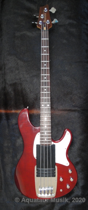
When I received it, the instrument was in perfect shape cosmetically and technically, except the string grounding was no longer functioning. This is a very common thing. Some use stranded wire spread apart, but this one uses a rigid wire under the bridge. After so many years, it lost its contact to the bridge plate by working itself into the wood. A piece of copper foil wrapped around this wire that spreads under the metal now assures solid contact to the bridge. After adjusting neck relief and action the pickup appeared slightly low, but would not come out after releasing the screws. The pickup happens to be supported by two large stripes of foam along the long sides which, even after more than 20 years, were functioning, but reluctant to expand due to the compressed position they have been in for so long. I replaced them with fresh ones. The pickup cavity is meticulously screened with conductive paint and well grounded, which is not common even with top notch guitars. So is the electronics compartment. Guitars should always be screened, regardless whether their pickups are hum-bucking or not. There is more interference than just hum. I found that out the hard way with my L-2000.It uses a barrel jack which, despite their inherent fragility, works flawless. The jack also points rather to the side than downwards, which helps to get the plug out of the way in a seated playing position. The preamp uses two TL062 amps, which should amount to a current draw of below a milliampere. That is the low-current version of the TL0xx series and not exactly the one with lowest noise. So when treble is fully boosted, some slight hiss is audible, but this is a setting that does not sound natural anyway and thus won´t be used very often. The Ibanez ATK is said to be a "Stingray Killer". It was probably Ibanez´ answer to Musicman´s introduction of the Stingray bass. While I don´t think it means any danger to the ´Ray, it gets into its territory alright. It has a class of its own and it´s certainly more flexible than the ´Ray, which is a one-trick pony.
The guitar has a proprietary pickup consisting of two single coils and a dummy (core-less) coil in between (hence the name triple coil). They chose to use the neck side coil for a single coil-ish tone and a parallel mode for what must have been their take at the ´Ray. All positions are hum-free. The third switch position (lever leftmost, "traditional") is the very same single coil slightly damped. I personally found this setting useless, nothing that could not be had with a tweak of the treble knob. Otherwise the pickup sounds great. I see entirely no single reason why it should be replaced, as some do. Back To Index Expanding Source Selection Capabilities After having played with it for a while and after having gained some experience with my pickup switching games I thought that it was a shame that they had wasted the other single coil tone. From my past experience I knew that singles, even in the same package, do sound different. Likely more useful than their "traditional" position anyways. There is a schematic by Cadfael[2] that I used for reference. The way he drew it suggested that the lost position could be used hum-free too, but it was not 100% clear. Like always, there was a chance that the whole effort would end in a failure. But I was fairly positive and it did work out a treat.
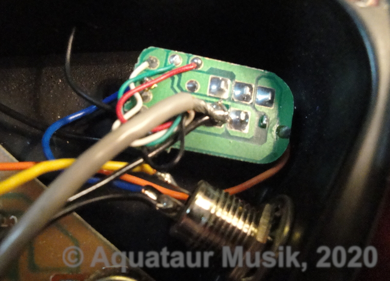
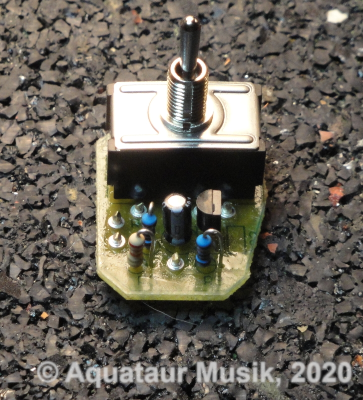
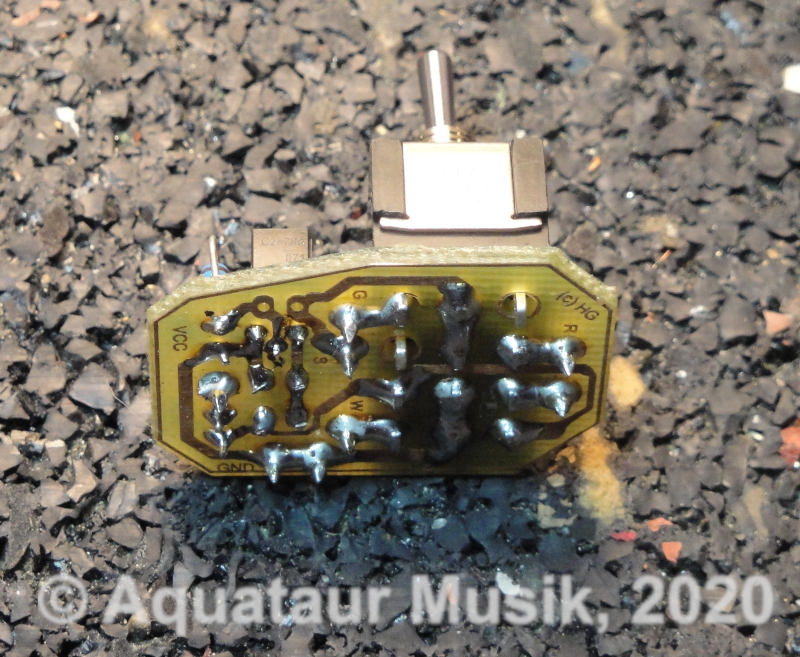
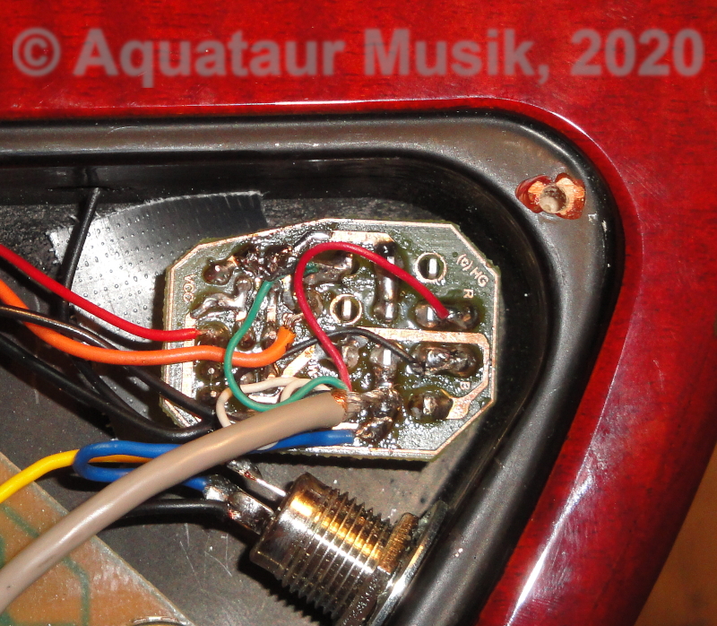
The switch needs to be replaced by a 4 pole on-on-on switch (the original one was a 2 pole on-off-on switch). Luckily, the switch is not mounted to the main PCB, but has its own little PCB. The new assembly fits into the cavity nicely. Note: you may not be able to get hold of the exact model switch specified, plus there is some caveats regarding those switches. I have written a special document dealing with that.
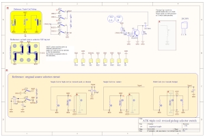
Since I liked the tone the rightmost switch position generates (parallel mode), I wanted to retain that, which requires a small voicing cap in parallel (2n2). I tried other caps with my cap switching rig, but this seemed optimum anyways. The single positions do not exhibit that exaggerated resonance peak of the parallel position, which stems from the voicing cap. It makes this position sound overly bright, which adds nicely to the Stingray flavor. In fact, omitting the parallel voicing cap brings the three available tones dramatically closer together, so this center position really benefits from a cap. A parallel cap will generate a peak with a certain Q, sometimes too big because which can be perceived stinging, like a wah pedal. This can be tamed with a parallel resistor, like they did in the "traditional" position. However, the singles did not sound better to my ears with a voicing cap. Voicing is a matter of taste, and one might decide that the single positions benefit from a cap, too. Now this can be most easily accomplished by using one of the ground switches, which do not even interfere with the center position tone.So, the center position was decided to need a voicing cap. Unfortunately, no pull-to-ground position was left empty on the switch in parallel mode that could accommodate this dynamic switching function. But wait, there are two unused pins (7&12) that pull down to ground potential when one of the singles is activated and float otherwise, and not when both coils are activated simultaneously. Now this sounds suspiciously like digital stuff and asks for a pull-up resistor and a transistor inverter. A low signal is generated by any one of those two positions called (/SGL). In parallel mode, the resistor pulls it high and activates the transistor. Now, although it would probably work, this is not a normal transistor, but rather a specialized "mute" transistor[3]. Those have been given special properties that make them particularly well suited for shunting signals to ground, or, as in this case, shunting a capacitor to ground. This works great, I have used it before, even in tube amps. The specialty about this type of transistor is that they can handle negative signals. If driven strongly, those transistors can achieve on-values of a few ohms. Even with the fairly weak drive I chose as a compromise between battery life and function, 25 Ohms are achieved, which is plenty for bringing the voicing cap into play. The added circuitry will pull 400µA of current from the battery worst case, which, at average, is about as much as one of the op-amps do. Overall current draw will be below one mA.For all practical purposes, the coil(s) then "see" a parallel cap and form a resonant circuit - like the original does. The additional components around are there to minimize audible noises caused by switching transients and prevent signal corrosion by dirt on the driving voltage.
Phew. The assembly worked right away. All positions are hum free and work as before. The new position is different and eminently useful. As one would expect from a position close to the bridge - it has growl. J-Bass friends will like this. The change was easy enough to justify the effort. As half expected (from the Cadfael[2] drawing), the original single coil is the neck position. By mounting the switch as depicted, Neck is selected when the lever points towards the neck, and, you guessed it, Bridge the other way. Center is parallel, what used to be the rightmost lever position in the original. Both original tones are retained exactly, and a new one is gained cheaply. Let me know if you find any of this useful. Commercial exploitation only with my written consent. Back To Index Sound Samples The subsequent recordings have been performed using the following setup and no further processing:
Use quality speakers or headphones or you won´t hear any difference.
Back To Index Reference [1] Gary Willis on bass ramps: https://bassmusicianmagazine.com/2014/03/the-evolution-of-bass-ramps/ [2] Cadfael´s (no longer so) small collection of e-bass schematics, V4.27 (p.291): http://www.ak-line.com/medium/Bassschaltungen.pdf [3]Jim Keith: Muting Transistor Attenuator Circuits and the 2SC2878, https://www.electroschematics.com/muting-transistor-attenuator-circuits-2sc2878/
Update History
MAIN PAGE>MUSIC STUFF>ATK |
||||||||||||||||
| MAIN PAGE | MUSIC STUFF | IMPRESSUM (c) 2020-25 AQUATAUR Musik & Elektronik |