G&L L-2000 Modding Study
A Study On Extended Pickup Configurations
And Voicing
last update: Jan 29, 2022

Copyright 2019-2022 by H. Gragger. All Rights Reserved. All information provided herein is destined for educational and D.I.Y. purposes only. Commercial re-sale, distribution or usage of artwork without explicit written permission of the author is strictly prohibited. The original units  with their associated  trade-names are subject to the copyright of the individual copyright or trademark owner. The Author is by no means affiliated with any of those companies. References to trade names are made for educational purposes only. By reading the information provided here you agree to the Terms of Use.
MAIN PAGE>MUSIC STUFF>L2000
Index


Measuring MFD Pickup Specs
Nomenclature: New Switching Functions Demand A New Name For The Switches
Evaluation: Why Do Players Consistently Revert To Passive Mode?
Exploring Existing Groundwork And Setting New Goals
Circuitry Overview
Making The Changes
Voicing

Hands-On Experience
Active Noise Reduction For Single Coil Mode
Passive Noise Reduction
References And Recommended Reading
Sound Samples
Update History


picture of the guitar (click on the picture to load larger image)
G&L L-2000 Bass.

A bass launched by Leo Fender† 1980 after his departure from Music Man. As salesman rap has it, it is the best, most versatile bass Leo ever made.

The foundation of the L-2000 is a pair of Magnetic Field Design™ (MFD) humbuckers and what they call the Tri-Tone system: a trio of mini toggles for pickup selection, series/parallel signal routing and active/passive operation. (It defies logic what is tri-tone about it).

The output of those pickups is massive due to the MFD design, but very bass heavy. Some folks from the D.I.Y. community have invented schemes to exploit the idling potential of creative coil interconnection beyond plain parallel native mode and all fancy tones that are possible by that, all with some shortcomings and trade-offs.

In the following I will show options previously not found or at least not published. In the process, many traditional concepts were put to the touchstone, new subjects arose and were evaluated on behalf of decision making. They will appear in a loose, not necessarily consecutive order. Sometimes they created more questions than giving definite answers.
A work in progress
- hence the title "study".
 
Although this may serve as a cook-book recipe for modding, I hope that, since an increase of options is likely connected to an  increase of confusion, the kind reader chooses wisely what promises to serve her/him best, before firing the soldering iron.

Sometimes, less is more, but then again...


"Too much of a good thing can be wonderful!"
- Mae West

Back To Index

Measuring MFD Pickup Specs


Coil (-Pair)
Mode
Magn. Pol. L (H)
Q
C (pF)
R (kOhm)
Test freq (kHz)
Phase (deg)
Yel-Grn
Single North 3.3
4.1
-
-
3.0
+76.0


-
-
92
-
200
-86.5


-
-
-
5.0 DC
0
Wht-Blk
Single
South 3.4
4.3
-
-
3.0
+76.7


-
-
89
-
200
-88.0


-
-
-
5.1
DC
0
Wth>(Yel+Blk)>Grn
Series
- 8.0
4.0
-
-
2.4
+76.1


-
-
56
-
200
-87


-
-
-
10.0
DC
0
(Wht+Yel)>(Blk+Grn)
Parallel
- 1.95
4.3
-
-
3
+77,0


-

162
-
200
-88,0


-
-
-
2.5
DC
0

Used measurement equipment:
  • Hameg (Rohde&Schwarz) HM8118 Programmable LCR-Bridge (L and C)
  • Philips PM2519 Precision Multimeter (R)
A note on the measurements. This RLC device is, despite its name, not a classical bridge instrument. It measures impedance and phase angle of the device under test and identifies the component according to a phase diagram (positive phase values: inductance, zero: resistance, negative: capacitance).

Since a guitar pickup comprises a parallel resonance circuit (inductive on lower frequencies, capacitive on higher frequencies with zero at the resonance), the device operates in parallel mode. Impedance changes wildly over the frequency range, and so do readings for L and C. With a conventional 100 Hz reading for L you may get a reading of 22H at a meager phase angle of +22deg. Readings become fairly consistent around some low kHz value for L, while the one chosen was the one that yielded the best phase readings. C measurements yielded the best phase values at the top selectable frequency. Resistance is measured in DC with a respectable instrument.

All values are rounded to the nearest comma. Precision beyond that was considered ridiculous. Also, I just measured one of the pickups (neck).

Virtually all low-budget commercial L-C Bridges use a different measurement principle and a limited set of frequencies, and since nobody documents those things, it is to be questioned how reliable those measurements are. Indeed, I do not claim perfection too, since there is always leeway. However, those values may serve as a reference point.

Determining magnetic polarity:

In Harmony with the information on Guitar Letters the north coil is the one that attracts the south pointing compass needle approached from the string´s side. According to this specification the coil closer to the neck (Yel-Grn) is a north coil (The side of the pickup that has two mounting screws
points towards the lowest string).

Caveat:


"Wer viel misst, misst viel Mist!"
- German saying (a word game meaning:)

"Who measures a lot, measures a load of horse-dung!"

Back To Index

Nomenclature: New Switching Functions Demand A New Name For The Switches

With the advent of complex coil interconnection circuitry, some nomenclature commonly used within this context has to be revised to describe phenomena previously non existent.

If those terms are not made clear, it is impossible to understand the following elaborations.

For example, in a basic two pickup system consisting oft two single coils, one at the neck and one at the bridge, one may find a 3-position selector switch, one for neck, one for both and one for bridge position.

Now this may be classically called pickup selector switch, which, since it has no secondary function, also serves as source selector switch.

For instance, a Les Paul type guitar traditionally has a pickup selector toggle switch, maybe adorned with some coil splitting functionality restricted to one physical coil cluster. Coil selection (and thus interconnection) is equivalent to the source selection.

A classical Strat has three single coil pickups and is equipped with a three-position switch. Each position selects one coil. Later models have a 5 position switch that also allows for intermediate settings and combinations of adjacent coils. Still the coil selection (and thus interconnection) is equivalent to the source selection.

Even later connection schemata arose that made complex interconnections possible like series and non-adjacent coils. Those clearly exhibit a distinction between coil (= pickup) selection and switch position. A switch position begins to select a fixed sound-scape. This is a performance selected feature rather than a recording session feature, which is the approach Dan Armstrong has taken with his Superstrat switching scheme. Lester Polfus (see later under “voicing”) has explored a similar path with his Les Paul Recording guitar. Similarly, one tinkerer modified his L-2000 with three three-position switches that allows for all imaginable interconnections – not necessarily a performance approach.

Scarcely however people have gone the way to the end by also incorporating individual “voicing” caps into those positions or dummy coils where needed.

In the case of the modded L-2000, the previous pickup selector switch (the one closest to the neck) loses its direct coil cluster fixation and becomes a source selector switch. The center switch (series/parallel) maintains its original functionality, but complex coil interconnection, beyond fixation to a cluster of adjacent coils, is transferred to a newly introduced  three-way switch, best called parallel pair selector.

In this case, any pair of coils, possibly spreading over non adjacent coil clusters, may be selected (such as inner pair or outer pair), which if source selector is in both mode will be a humbucking (parallel) pair, but in solo (neck or bridge mode) a 
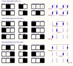
single coil. See the reference chart later on.

For clarity, a distinction has been made between coils belonging to one physical cluster of adjacent coils (hereafter native mode) and two physical units (hereafter cross mode).

According to the previous differentiation between performance and recording switching schemes the scheme presented in the following is positioned in-between. It is experimental and work in progress. Ideally, there should be a “P”, a “J” and a “S” position and little more.

The widely used nomenclature „single inner“ resp. „single outer“ is a misnomer, since it indicates single coils, but it is actually a hum canceling pair (for both mode at least).

This nomenclature stems from the fact that one coil out of physically stacked up pair is used together with one single coil borrowed from the pair across, hence the name cross-mode.

It is replaced by the terms inner pair and outer pair, referring to the physical arrangement of 2+2 coils at the neck resp. bridge side. "Inner" and "outer" makes only sense in reference to this arrangement. Nevertheless, true single coil operation for all four coils is possible, it comes into the bargain. Refer to the pickup selection chart for more information.


Back To Index 
Evaluation: Why Do Players Consistently Revert To Passive Mode?

Some users of the L-2000 insist on using it passive, with volume and tone pots dimmed. Why? We want to understand this, because there may be things we can optimise into the bargain. This also builds some foundation for any alleged voicing later on.

Some aside to technical explanation is inevitable.

Every pickup basically is a resonant R-L-C circuit (winding resistance, inductance and winding capacity), which forms a higher order resonant low pass. Guitar Letters explains this well.
Such a circuit on its own will exhibit some ringing at the cutoff frequency, sometimes substantially dependent on its Q.
Although this may be perceived as extended treble range, the ringing is usually not appreciated. Think of a wah pedal halfway back at a fixed position – good for an effect, but not for always.

Technically this peak can be modified by two factors:  a parallel cap and/or a parallel resistance.
An additional cap will add to the winding capacity and shift the peak towards lower frequencies. An additional load resistor will bring the Q down and with it the ringing.

Our pickup always exists within  a practical electrical environment, in the vicinity of a volume pot and a tone pot at least, so a certain load resistance is always there. Humbuckers are more sensitive to load than singles, that´s why you always see recurring pot values of 500k versus 250k in single coil environments.

A passive treble cut pot, when at 100%, presents some more load, say 250k, which totals in 120k together with the volume pot for a single coil. Turning tone down just a little may be enough to remove the hump and thus the ringing. (Remember: that´s what many players say they like...).

Turning it down completely will bring the tone cap in parallel to the winding capacity and create an artificial resonance at a ridiculously low value, which is unfortunately beyond good or bad to be useful for stock cap values. All passive guitars work like that.

Now we have not yet plugged the guitar into an amplifier in our mind experiment.

Adding a cable adds more capacity and more load resistance dependent on the pot´s settings, so that there may be a sweet spot of all settings that sounds good. Of course passive circuits also introduce  other imponderabilia that can wreck the signal.

That´s where the active mode enters. However, this way has not been gone to an end with the L-2000´s stock circuit. Dropping all load factors – too much brightness, too much ringing and that consistently. Since the built in amplifier is configured for some treble boost even in the normal mode, letting alone the treble boost option, this can only worsen things for some.

Happily, some small capacitors and resistors before the buffer can tame any of those things and thus introduce all of the merits of passive mode without its drawbacks. It so happens the L-2000 already has a 1nF cap in parallel by definition (this is the one soldered onto the bass pot).
This, to my taste, is too hefty. See later in the section on voicing.
Our extended switching circuitry offers some unassigned positions for that into the bargain.
Since this procedure is really that easy and cheap, it makes me wonder if the ones who devised the circuitry did only have their sales numbers in mind, saving caps worth cents... It brings more money to sell another instrument rather than have just one that does all you want...

Back To Index

Evaluation: OMG Mode,  More Boosts That Are None And Boosts That Chase Their Own Tail

In 1982 Leo Fender filed a patent (US.-Pat. 4,319,510) for splitting humbuckers that do not have all leads accessible, also known as three wire humbuckers.
This is in fact astonishingly simple. As different to shorting out a coil entirely, a capacitor shunts frequencies out. Choosing the capacitor´s size wisely, 50 Hertz hum cancellation remains intact. However, higher frequency hum (such as from switching electronic appliances) will not cancel. Making the capacity smaller will work better, but let increasing amounts of low frequency content through.
On the L-2000 basses, Leo was probably trying to achieve a pseudo single coil sound, which is less boomy, and in the verge of trying different caps found the bass boost attractive. How the term OMG came about is unknown, since this is recent social platform lingo.

By shorting some of the treble content out, bass content appears louder. Although just cutting and not boosting, this mode was called „bass boost“. All is relative. Unfortunately, together with the fixed 1nF voicing cap, this mode sounds pretty dark. Maybe interesting for some retro sounds, but not for contemporary sounds.
Again this is no real coil splitting, it is a humbucker wired pseudo single coil. There is no coil shorted out with a hard wire bridge.

OMG mode lead to many complaints by musicians, because hum suppression is, like in all single coil circuits, inferior. Moreover, Leo could have at least the center position (both) humbucking, which
was recognized by the DIY community[1], but never cured by the company. Conversely, they decided to drop OMG entirely on later modes, such as in my specimen of the bass.

My personal opinion is that the series wired pickups are powerful enough the way they are - without "boost", and that it is somewhat awkward to generate a bass overload first and then use treble boost to remedy that. The cat bites its own tail.

When working with new modes it became obvious that the volume drop between serial and all other modes was a nuisance, requiring a permanent re-adjustment of the volume pot.

The previous owner had made a feature out of this flaw by calling it the „rock switch“ - volume boost. Hmm. Rather make a small, adjustment on the volume pot if needed.
I found the idea great to equalize the volume levels by adding a series resistor where normally the wire bridge between yellow and black goes. Extensive listening tests in both active and passive mode and also some PC simulation did not indicate any change in tone.

Of course, OMG does not harmonize with that, but this was deemed questionable anyway as elaborated above. There is no need for pseudo humbucking if real coilsplitting is at hand.

However, by bypassing the dropping resistors with a cap, some partial "boost" of high frequencies can be achieved. Again, this is no boost, but treble content gets less suppressed. Why making half hearted attempts towards single coil sound when a brighter sound can be achieved another way while maintaining full hum canceling functionality?

Back To Index

Exploring Existing Groundwork And Setting New Goals

By far the most of the mod tips I could find are limited to the installation of a three-position (on-on-on) switch, selecting between serial, parallel, and one single coil combination, and possibly a push-pull pot for extra switching, which basically replaces the existing two-position serial/parallel switch.

All the those attempts to maintain the original possibilities (serial, parallel) plus at least two cross-connections (inner/outer pair) without inviting other penalties, failed to my knowledge.

There is a limited amount of switching possibilities that manipulate the „hot“ side of the pickups, and even more limited for the „ground“ side, since G&L have decided early to connect a screening ground plate to one of the coils (green wire). Drilling some holes for extra switches or the like was not an option, being  commonly associated with a loss in resale value.

A guy named Femto has devised a switching method using the stock serial/parallel switch plus an extra on-on-on switch, which would have to take the active/passive switch location (this one moving to the switch of a push-pull pot), yet functionally being very similar to the method devised by me.

Femto manipulated the ground sides of the coils, which, although this appeared to work for him noise-wise, might invite trouble due to the ground plane floating, that is mounted to the bottom side of each physical unit. It is likely that people were reluctant to adopt his method because of this fact.

However, combining both high side and low side switching turned out to work flawless with a compatible switch layout.


The goals for modification thus were set to be:


  • exploiting all coil interconnection methods (serial/parallel/single/cross-connection) while maintaining the existing switch layout to avoid degrading resale value
  • equalizing volume
  • voicing

Back To Index

Circuitry Overview

In a nutshell: the newly devised switching scheme keeps the original serial/parallel switch, except that the range of available parallel modes has been expanded, determined by the setting of the parallel pair selector configuration switch. Dependent on the setting of the source selector switch, all four individual coils can be addressed in true single coil mode too.
The parallel pair selector switch physically resides in the space, that was previously occupied by the active/passive switch, whose functionality moved onto a push-pull switch linked to the volume pot knob.
Note: treble boost mode has been dropped as mentioned earlier.

pickup selection chart - click! (click on the picture to load larger image)
Pickup Selection Chart:

The parallel pair selector switch allows for three positions:
  • inner pair (lever towards the neck, pairs one of the neck with one of the bridge coils,
    here referred to as cross mode)
  • parallel (lever centered, pairs physically adjacent coils, here referred to as native mode) and
  • outside pair (lever towards the bridge, pairs one of the neck with one of the bridge coils, here referred to as cross mode)

When both is selected on the source selection switch, those positions are hum canceling. Since the coils are arranged N/S - N/S starting from the neck, the cross-mode arrangements xS - Nx (inner pair) and Nx-xS (outer pair) are hum canceling as well as the native N/S arrangements.
Note: In solo mode (e.g. neck only), out of the selected pair, although both coils are active, only one will contribute to the output signal - the one residing in the source selected (neck in the example), hence a true single coil. This one is subject to hum as all single coils are. Determining which one out of the two adjacent coils is currently active is slightly awkward and is not always in direct relation to the switches´ lever position due to the fact that one has been eliminated out of a cross-pair. Logic has been optimized in so far that the lever points towards the inside of the guitar body in inside pair mode and towards the outside in outside pair mode. Thus, only if bridge solo is selected, the parallel pair switches´ lever points to the correct single coil, but this is reversed for neck. This is inevitable and a small problem.

 Humbucker pairs in cross mode may have an slightly inferior hum suppression capability due to a greater “magnetic aperture”
download
                            serial mode chart
Download  serial mode chart (click on the icon to download)
download
                            serial options chart Download serial options chart 
download
                            native pair parallel mode chart Download native pair parallel mode chart 
download
                            outer parallel pair cross mode chart Download outer pair parallel (= cross-) mode chart 
download
                            inside parallel pair cross mode chart Download inner pair parallel (= cross-) mode chart 

Back To Index

Making The Changes
  • The threading of the 4pole on-on-on switch I used (Knitter Switch MTA 406 PA) appears slightly shorter than the C&K variety, so it needed to go slightly deeper into the wood. The usage of any machine operated drill was avoided at all cost, since this eats itself into the wood way to fast. A few turns by hand were enough.

Note: knitter switch MTA 406 PA datasheet information is erroneous on the pin layout. The layout is equivalent to the ubiquitous C&K 7411 and Multicomp 1M46 switches. WARNING: I just received two switches from them that DO adhere to the Datasheet. Measure before you solder!
Update: refer to a
special document on those switches for more information.

  • I looked for  a good quality push-pull volume pot with a solid 6mm shaft like the other pots on the L-2000. There exists one from Alpha, but this seemed unavailable. The one chosen is a CTS 250k PUSH/PULL 3/8", which fits just perfectly inside the cavity. It has a very smooth volume reduction over its travel and also exhibits the same friction to motion as the others do. Its thread too, is a bit short, but using a bigger diameter lock washer that sits on the pot body rather than the small mounting rim works well.
  • It also comes with a 1/4” knurled shaft. Unfortunately, dome knobs for knurled shaft pots are not available hereabouts. Fortunately, you can buy small brass sleeves that slide over knurled shafts and make 1/4” solid shafts out of it. The dome speed knob´s bore was increased to 6.5 mm with a stock steel drill and this works great.
  • The ceramic treble bleed cap was replaced by a good quality cap on the go.
  • The push-pull switch activates passive mode when pulled, but this is a matter of  taste.
  • The barrel output jack was replaced by a new one since it permanently interrupted the signal when the slightest sideways pressure was applied onto the jack[2]. Removal was easy with a screw extractor (the type that has reverse „threads“ on it). The jack does not even get destroyed by this. It just screws out. Unfortunately that the new jack appeared to be no cure. Signal went intermittent when you use a long flange plug and apply sideways pressure. So using angled plugs and folding the cable back under the strap is paramount if the kind reader insists on keeping the barrel jack.

    The barrel plug is just inferior. A disgrace for such an expensive instrument. It is beyond comprehension why they used it, probably to distinguish themselves more from other manufacturer´s products visually. Internet forae are full of complaints about this nuisance, and many owners have decided to replace it by a conventional jack:

picture of replaced jack
(click on the picture to
load
larger image)
Soon before long, the barrel jack was replaced by a standard jack together mounted onto a metal football shape mounting plate. The procedure is described here[3].

An oval (a.k.a. football) jack plate together with a standard Switchcraft short Ľ“ jack was mounted (a Gibson style square jack plate appeared almost too big, extending into the beveling) – end of discussion and end of signal problems.

Folks doing the same before worried that it may be a problem to drill a large enough hole without slipping and damaging the guitar finish. Not at the least. I used a stock metal step drill in a slow running cordless electric drill to enlarge the hole to 20mm just at the rim, yielding a somewhat conical bore.
A 20mm Forstner bit now fitted perfectly into this bore, so no danger of slipping. The wood is soft enough that a very slow drilling speed can be used. Some more gentle drilling and the hole was through. No chipping, nothing, a razor sharp cutout. A five minutes procedure and painless.
  • Another questionable omission was the unscreened electronics compartment cover plate. This is ridiculous, since the compartment itself is paint screened.
    A piece of self adhesive metal foil was applied to the plastic plate. A small strip of  copper foil was folded and glued over the cavity´s edge and soldered onto a ground point so that it makes contact to the cover´s foil, at a location near the output jack where the back plate is screwed onto the body for good contact.
  • The wire to the preamp that does the treble boost was be removed.
  • The preamp itself got wrapped inside a piece of self adhesive tape to prevent contacting anything.
The cavity is now quite crammed, but serviceable since I left enough slack on the wires.
  • Pickup height. While not being a new feature, this subject belongs to the changes made to the instrument: during slap playing, the E string easily thunders into the pole pieces, with an according sharp snap from the amp. With the pickups fully down and the spiral spring underneath fully compressed, they still protrude about 10mm from the body. The remedy was to shim the neck slightly so that all strings are elevated somewhat. This of course requires raising the bridge again to restore the previous action.
Back To Index

Voicing

Now the switching stuff has all been sussed, a whole new can of worms is torn open – voicing[5].

Browsing through the settings invariably involves a change in perception of treble, mid and bass content, some subtle, some heavy. A minimalistic guitar setup will be equipped with a treble control, which, as we saw earlier, can tame the resonance peak and cut some high. The second resonance that occurs when the pot is at zero (caused by the treble cap), is usually too extreme to be useful. So those positions remain essentially raw and untreated sonically.

Lester Polfus, better known as Les Paul, was confronted with exactly the same problem back in the seventies with his Les Paul Recording Guitar, and he solved it by providing a rotary switch with an array of caps, not different to the C-switch devices available today.
He aptly called his guitar recording, since, in a performance situation, few would have been able to cope with all those knobs and switches.
These days, things head towards performance selector switches (such as in those fancy aftermarket 5-way Strat switches), which select between “sounds” consisting of useful coil presets and potentially voicings.
This means a deliberate step backwards from Les Paul´s idea for the sake of simplicity and performance, but he wanted it all.

Despite thousands of schemes available on the internet, rarely anybody exploits the whole potential of tone shaping those positions.

A 1nF cap (stock) is already active for all positions, which to my personal taste was too much. It was replaced by a 680 pF Styroflex cap. This made the series signal even more pristine, alleviating the need for an active treble boost even more.

First listening tests on the untreated parallel modes and particularly the single coil modes revealed a pretty trebly, sterile tone, reminding of early Stanley Clarke recordings. A test jig was put together quickly, nothing different than what is known as the commercial C-switch or tonestyler (a rotary switch with a rake of small caps) and small caps in the nF range (around 2.2nF)  were found for each position that brought the resonant frequency down to an pleasing value before tone was becoming honky.

Naturally, single can take more capacity than parallel, but due to the lack of unoccupied switching positions a compromise value of 2.2 nF was chosen for all non-series positions. Tone gets much more mellow by this, without sounding honky or bassy.

The acute reader will have noticed, that this demands another switching element in the series/parallel switch, which is non existent unfortunately, but some crafty solution has been found, remaining my ace card for the moment.

Any excessive resonance peak (“Q”), perceived as stinging quality, can further be tamed by dialing the treble pot down just a hair, long before the treble cutting action itself comes into play, so individual Q-shaping resistors were equally abandoned due to the lack of switching positions.

"Passive tone" despite buffering was re-contemplated. A typical guitar cord may exhibit 100pF/m capacity, a 6m cable will thus easily have 600 pF. Together with the built-in load 1 nF capacity this is a fairly hefty load for a passive system - too big for my taste as mentioned, but some seem to like it.


Back To Index
Hands-On Experience

With all this extra switching, you can always leave the parallel pairs selector in center position, in which case the bass behaves exactly like stock, leaving aside volume equalization and voicing. It certainly looks stock. Flipping the parallel pairs selector into another position, you´ll have powerful presets ready at the flip of a switch.
  • Volume, after equalization,  seems subjectively fairly constant across the different pickup modes. It is still slightly bigger in serial mode, but was left at that.
  • Astonishingly, once loudness-equalized, a parallel mode (provided using active mode) does sound very similar to the corresponding serial mode. This is probably where the axiom louder sounds better is striking. In fact they are so similar, that for a future build series mode may be dropped entirely without losing.
With the switching given, all extended pair modes (inner and outer pair) are parallel modes. Theoretically, there is a possibility to connect those in series too, but little promises to be gained as stated before.
  • Parallel and single modes do cope better with passive mode if an additional load is present.
  • Series is still the most bassy, but with an increased clarity due to the bypass caps and the reduced stock voicing cap. With some hundred picofarad worth of cable capacity, tone heads towards dark as expected -  which is why we go active for a start. Parallel and single modes however  do cope better with passive mode if an additional load is present.
  • Cross modes sound very beefy and growly. Do they remind of a Stingray? Maybe. People say not even all Stingrays sound like a Stingray. Both modes have a different mid-range compared to all other modes, even compared to each other. There for sure is a certain mid-scoop that the ´Ray´s have too.
  • Single (bridge) mode reminds of a J-Bass, but  is prone to noise as expected despite shielding (this helping nothing against magnetic interference...). Any individual single out of the two adjacent pairs can be activated, although it is a bit awkward to select them (see the pickup selection guide).
  • Singles sound very raw and into-the-face. Very attractive too. Again, P-bass is not P-bass, J-Bass not J-Bass,  a single pickup sure gets into their ball park.
I decided that a general load simulation was neither necessary nor useful. Leaning more towards modern sounds,  passive mode was not considered attractive, but if one wishes, one switch position is free on the active-passive switch (volume push/pull switch) which could activate a dummy load. In this case, active and passive tone would not differ much, but passive tone (as mentioned above) could be reproduced reliably and repeatably independent of subsequent loading circuitry.

All of those features accessible with the new circuit have their merit, but time will tell if the increase of switching options or -methods itself  is a blessing or a curse.

Back To Index

Active Noise Reduction For Single Coil Mode

After some playing, the single coil modes do not sound particularly attractive or reminiscent of other basses´ sounds*, but they are different and interesting and may as well be used. Unfortunately they are prone to hum. Maybe, due to the powerful nature of the pickups, more than others. I tried to do something about this and made up a large area aircoil (not unlike the Suhr silent coil) to passively cancel out hum frequencies.

* Maybe I expected to have a Precision sound or a J-Bass sound at hand, and while it surely crosses into that territory (like any similarly built pickup in that position will...) I found there is no such a thing like THE XY sound. There are several web sites that try to carve this out and they had to admit that they failed, because over the years so many models with different body and neck woods resp. shapes and surely differently wound pickups had been made. This can´t be generalized.

self-made backplate bobbin housing an
                          aircoil
Self-made back plate, an epoxy bobbin with an aircoil inside: (click on the picture to
load
larger image)

This worked and continues to work flawless on my Stratocaster. It makes it virtually hum free without changing tone.

Unfortunately, due to the heavy signal coming from the L2000´s pickups, the aircoil with a typical rate of turns is too weak.

self-made backplate inside view
Back plate inside view: (click on the picture to load larger image)
The inside is covered with foil for screening purposes. Can be detached from the electronics PCB. Weight is negligible.

new
                          electronics PCB
Experimental electronics PCB: (click on the picture to load larger image)

I devised a crafty active circuit with switch position detection, dynamic phase reversal and adjustable gain. To the left you see some C-MOS IC´s that detect switch positions. Hum cancellation is only active during certain positions. This part also dynamically connects voicing caps dependent on the switches´ positions, so the newly gained modes may stay balanced sonically.
Hum cancellation worked in some environments, but made things worse overall. The idea was dropped and basic functionality restored. The empty sockets you see stem from the IC´s pulled for this purpose.

The remaining circuitry is entirely optional. No need to change what is there.
The singles do still hum, but the rest is dead quiet.


Back To Index

Passive Noise Reduction

Now that all active methods to eliminate hum failed, I find myself back at the roots. While it is true that screening won´t help against magnetic interference, it will certainly help against  electrostatic interference. And true, some of what I hear, sounds like a harmonic of mains (transformer originated) frequency, without the fundamental.
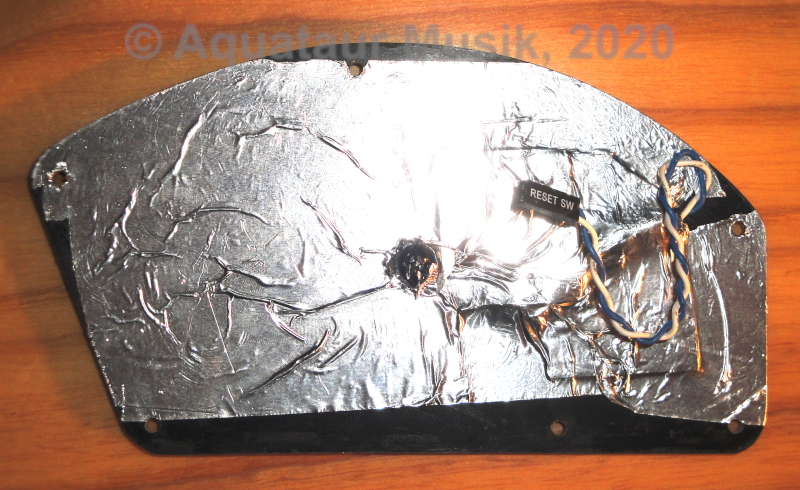
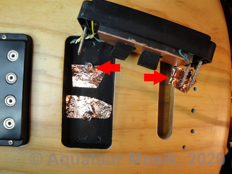
I opened the pickup cavities - and they are bare wood. Agreed, the guitar was never intended to be used with single coils, but even in humbucking modes it appeared vulnerable to higher frequent noises. To cancel those the "aperture" of the two coils is too big. People report that with screening they made even humbuckers quieter.

I have plenty of copper foil at home, but there is no space in those cavities. So I bought a small bottle of Humbrella screening paint invented by a German guy and allegedly preferred by luthiers. This does not consume any noteworthy space.
Three layers with drying time in between is recommended. With a small brush I even poked a little into the tunnels that go from the electronics compartment to the pickup cavities. The wires should be screened too. (See my hints further down on working with the paint)

MFD pickup underside
MFD pickups from underneath: (click on the picture to load larger image)
(picture taken after cavity painting)

Take a look at the pickup´s underside. There is a massive copper base plate with two green wires attached. One comes from the coil, one leads to the switching assembly. As stated above, the method Femto has devised to switch the coils from the ground side was ruled out previously due to the base plate grounding problem, but it looks this can be remedied no problem by adding a separate wire to the base plate. Soldering is no witchcraft, just make sure the extra wire is secured against pulling strain. So his method may prove useful in some respects after all.

painted pickup cavities
Painted pickup cavities
:
(click on the
pic
ture to load larger image)
A few hints for using the paint:
  • stay away from contacts. While the paint is not super conductive, it is low ohm indeed.
  • stay away from cables. They advise not to rely on the paint´s adhesion to plastics, but it adheres to cables like hell.
    While this does not harm the cable itself, it might make contact somewhere else.
  • the paint adheres greatly to rough untreated wood. From lacquered wood you can scratch it away with the fingernail after drying. Be aware that it stains blank wood immediately. Rough up lacquered surfaces as recommended, but be aware that steel wool debris will go flying to all magnetic parts. Better use fine sanding paper if you have the pickups in the vicinity like I had.

pickup cavities reassembled
Reassembling the pickup cavities
:
(click on the picture to load larger image)

The pickup cavities have two holes drilled to hold springs to push the pickup up (left arrow). A piece of foam pushes back (the foam was already a bit deteriorated and was renewed).

I had to widen those holes slightly, because the springs are really tight in there. After painting with conductive paint and re-inserting the springs prior to assembly, I inserted small strips of copper foil between the spring´s windings (bottom arrow).
Once the spring pushes down and gets compressed, the copper foil makes contact to the paint. Since the foam pads are right beside, those push down too. The springs themselves work against the bare copper baseplate, which by itself is grounded.

Note the piece of copper foil on the right. I wrap this around the piece of wire that grounds the bridge (and strings), which was already a bit recessed in the wood.


After assembly, I inserted a small strip of copper foil in a crevice right beside the pickups to contact the paint and measured some 50 Ohms against ground. This is absolutely perfect.

electronics compartment repainted
Repainted electronics compartment
:
(click on the picture to load larger image)
The electronics compartment is insufficiently screened. There is conductive paint inside properly, but incomprehensibly, they failed to screen the back cover plate. This is simply a matter of applying foil to the plate, which conveniently contacts the rim of the compartment - but not on this guitar (see the pictures above).

G&L did not paint the rim with conductive paint. But this can easily be done with the newly acquired wonder paint. Make sure to paint copiously over the already existent paint a little down the side walls to ensure connection and stay away from all electrical connections inside.

Of course I also painted the cavity I drilled in order to replace the dreadful barrel jack
as explained above. Insulate the jack inside!

The arrow points towards one of few places where I spilled the paint (picture taken after drying before any further steps. No sweat, it does not adhere to shiny lacquer.

As expected, hum did not go down, but its higher frequent components did. The effect is subtle, but noticeable.
Let me know if any of this is useful or appeals to you.

Back To Index

References And Recommended Reading

Credits: Many threads on modification of the L-2000 have been sieved through, notably written by a guy named DavePlaysBass in talkbass guitar forum and BassesByLeo forum (several threads), by Femto and Ken Baker, who maintains BassesByLeo, all of whom I feel deeply indepted to. Credits also go to Ulf Schaedla in Germany,
probably the best source of information on pickups and voicing currently available.


[1] G&L L2K Wiring Mods Rev 4.1, 27-Dec-2117, by DavePlaysBass@hotmail.com, p.2
     Fixing Bad Designs: Barrel-Style Output Jacks - Hanff Guitar Repair
[2] Jack Replacement: (how to re-fit a new barrel jack), by Ken Baker from BassesByLeo
[3] Jack Replacement: (how to replace a barrel jack by a conventional jack), by BluesBassPlayer on BassesByLeo forum
[4] G&L Preamp Rev 2.2, 12/28/2017, by DavePlaysBass@hotmail.com
[5] Guitar-Letters: a wealth of information on pickups and voicing (in German language), by Ulf Schaedla

Back To Index

Sound Samples
The subsequent recordings have been done using the following setup and no further processing:
  • L-2000 modified as above, pickups as specified, all controls full. EB cobalt flat strings.
  • Warwick Pro-Tube IV, direct out
  • Recording device: Focusrite PC interface into DAW

Note: "inside pair" means _N B_ and "outside" means N_ _B. Neck single mode inside thus means _N _ _  and outside N_ _ _ etc.
Yes, more options, more confusion 8-)
On the single mode recordings, you may hear some hum, but worse, you may hear high frequent noises to a lesser extent on all  recordings. This comes from the proximity to the PC, although not necessarily hum. PC´s and neon lamps are the recording musician´s worst enemy. Recordings have been done prior to shielding.

(Names may be copyrighted by the associated copyright holder, no association with any of them)
Comparison serial / parallel (native) modes: Neck PU (serial first, parallel on second phrase)
Note how little difference there is sonically between serial and parallel modes when volume-equalized and when a buffer is behind to avoid tone sucking. A valid argument to ditch the serial modes if one wants.


Comparison serial / parallel (native) modes: Both (serial first, parallel on second phrase)


Comparison serial / parallel (native) modes: Bridge  PU (serial first, parallel on second phrase)


Extended parallel modes (cross-mode): Inner Pair
Does one of those two cross into Stingray territory? Guess it does. Decide yourself.


Extended parallel modes (cross-mode): Outer Pair


Single coil mode: Neck PU Outside (towards neck)


Single coil mode: Neck PU inside (towards bridge)


Single coil mode: Bridge PU Inside (towards neck)


Single coil mode: Bridge PU Outside (towards bridge)


Back To Index


Update History
  • Jan. 29, 2022: minor typo
  • Mar. 29, 2020: added special document on 4p3t switches.
  • Mar. 15, 2020: added passive noise suppression.
  • Mar. 6, 2020: added active noise suppression for single coils and sound samples.
  • Apr. 10, 2019: first release
Back To Index
MAIN PAGE>MUSIC STUFF>L2000
MAIN PAGE | MUSIC STUFF | IMPRESSUM

(c) 2019-2022 AQUATAUR Musik & Elektronik


foo