|
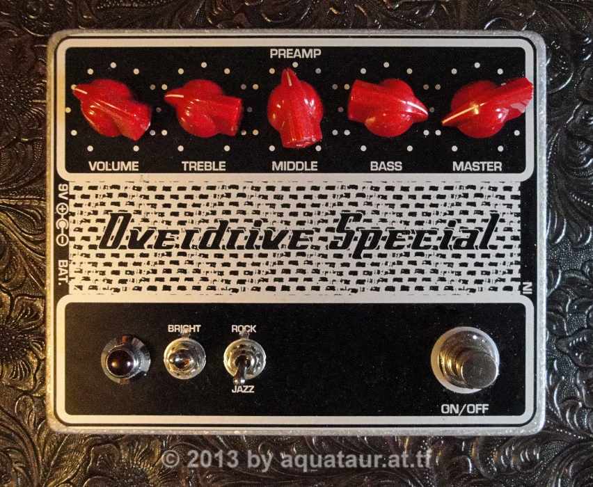
Overdrive Special (UMBLE by
R.O.G.) A stompbox tribute to xUmble type Amps last update: July 14, 2014 Copyright
2014-25
by H.
Gragger. All Rights Reserved. All information
provided herein is
destined for educational and D.I.Y. purposes only.
Commercial re-sale,
distribution or usage of artwork without explicit
written permission of
the author is strictly prohibited. The original
units with
their
associated trade-names are subject to the
copyright
of the individual copyright owner. The Author is
by no means affiliated
with any of those companies. References to trade
names are made for
educational purposes only. By reading the
information provided here you
agree to the Terms
of
Us. The working language
is kept in English as an aid. Read here
why.
|
||||||||||||||||||||||||
| MAIN PAGE>MUSIC
STUFF>UMBLE Index
Building Experience - Biasing Issues As usual, no
circuit I clone passes my hands without
modifications, usually straightforward basic
engineering improvements.
Back To
Index
In direct relation to the Fetzer Valve, I changed the fixed value source resistors to trim pots with a fixed portion (series resistance) to accommodate a wide range of j-fets (I did, however stick with the J201 because all others I measured would have needed substantially higher quiescent currents - not a good thing for a device that is operated by battery. Since the J201´s did not exhibit unbearable noise and performed well, those stayed... The drain pots were changed to 50k trim pots because it turned out that that the whole adjustment happened in the very low range of the pots. All j-fets were measured with a jig according to the one suggested in the Fetzer Valve document. The appropriate values for source resistors were calculated using the calculator on the bottom of this document, although it turned out that this was less than ideal sonically. It turned out that setting the drains to half-supply would not yield the best tone. A closer look with an oscilloscope and a frequency generator revealed that the resulting waveforms measured at the drains were nowhere near idling at half supply. Consequently, the adjustment range for the drain pots was narrower than expected, in fact for one transistor the optimal working point window was so narrow that it started sputtering as soon as the supply voltage changed even a small amount - unacceptable for a battery driven device. (This explains by the way why I never got my version of the Peppermill running satisfactory. It uses a fixed source resistor which certainly has too high a value). I fixed the issue by setting the source resistors to a lower value. Then the drain pots would adjust a balanced half-supply waveform. I set both of them so that the bottom half of the sinusoidal waveforms becomes more deformed upon excitation than the upper half, just as valve amps are said to behave, and that the idle voltage approaches about half supply. This sounds great. The source resistance thus may deviate substantially from the calculated amount, but this serves well as a starting point. Back To Index Further Deviations / Improvements
More Tube Tone - Power Stage Sag The Umble circuit does its job well, just like many similar overdrives surely do, but it only emulates the preamp portion of a tube amp. There are many other effects a tube (power) amp contributes to what is known as "tube tone", such as loose coupling of the driver compared to the stiff coupling of a transistorized amp. This cannot easily be simulated in the signal domain and I have never seen an attempt to do so yet. Apart from graceful signal shaping, one of the further virtues of a tube amp is signal compression, in this context better known as sag. Linear power supplies consist of a transformer, some sort of rectifier and capacitance. Dependent on the implementation, this chain also contains a certain amount of resistance (deliberate or inherent), which, under load, leads to a drop in the power stage´s supply voltage. A sudden increase of the input signal therefore yields a current surge in the output stage which in turn drops the supply rail somewhat. Fast power peaks therefore get compressed to an extent. This works like a compressor with fixed attack and (mostly also) decay time. The effective resistance together with the filter capacitors determines its time constant. Since this seems an important part of tube tone (which we are after right from the beginning...), let´s look at what compression, or, in this case, sag, does to signals. What Compression Does To Tone Signal compressors in general, as they are used in recording studios, serve (amongst others) the following purposes:
In short, they change the shape of the signal by potentially modifying its initial attack, its decay and its (perceived) overall volume. What is hidden within those actions is that by changing the signal´s waveshape you change its frequency spectrum. This appears important, so let´s look at that more closely.
This shows us how important the shape of the first transient is and how much sag type (or any) compression may change the envelope.
Compression by the way also makes the signal subjectively louder (since the decay portion of the signal appears more prominent), which, together with the graceful signal limiting of a tube stage, creates the impression that a tube amp can be played louder that a comparable solid-state amp (which may produce bad sounding distortion artifacts at the same power level...). From here stems the saying that tube amp watts are better than transistor watts... The exact mechanism of tube power amp sag and its time constants are well known and simple, but not easily to put into numbers. Also, this effect is distinctly power amp related resp. power stage supply current related, and can thus not easily be transferred to a preamp stage, be it tubes or solid state equivalents. However, this is not important if we want to emulate its effect.
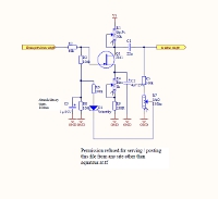
Intuitive Sag Circuit For The Umble The preamp stages are usually daisy-chained to the power amp supply and will drop too, but since we are talking of power amp compression and we assume the preamp runs at fairly low gain, this has not much effect on the signals passing the preamp stages. If, in contrary, a tube amp uses the input stages as signal shaping devices, as is done on master-volume equipped amps, the power stage may run low power and not exhibit any noteworthy sag. So, although a tube preamp distortion mechanism does depend on supply voltage (like all signal bounding circuits work against a boundary), one may not rely on the sag of the preamp for the effect. So intuitively, one may be tempted to use an R/C filter chain, such as in the original tube amp schematic which will cause a voltage variation with varying signal amplitude. However, in real life it is not the current drawn by the preamp tubes that cause a variation in their anode voltage (the j-fet drains in our case), but rather the the current drawn by the power stage. Preamp stages are biased about mid-supply, kind of class-a. What happens if a healthy signal comes along? The voltage on the drains rises!. How come? A class-A circuit always uses most power when it is idle. When the signal swings rail-to-rail (particularly if it clips) the device is off half of the time -> the current drops and the drain voltage rises. This circuit therefore is a clear failure. And I ran into it ;-) Another reason for leaving the supply alone is the fact that our may j-fets shift out of bias. We don´t have the luxury of hundreds of volts of supply. So even more elaborate circuits like the punisher will fail. But the caps stay there with small resistors (56Ohms) - makes for a well filtered supply. A Sonic Analogy To Power Stage Sag So fiddling with the preamp´s supply is not working. But as mentioned above, the net sonic impact of power stage sag is compression, which can well be simulated in a preamp stage. As mentioned above, let´s apply known methodology to our problem ;-) Although O´Connor does not go much into detail on preamp stages, he does apply it to a single ended power stage, which has much in common with a preamp stage for our purposes.
Despite the fact that O´Connor strictly speaks of tube (preamp) stages in this context, we can safely apply this knowledge to our j-fet stages which are there to emulate tube preamp stages in the first place.
Installing the compressor in an early stage does not make sense, because we are not dealing with dozens of volts here like in a real tube stage. After the input stage the signal is small, not reaching clipping. After the tone stack it is even smaller and has to be recovered by the following stage. In order to have a useful control voltage range, the compression has to happen in one of the later stages. I chose to use stage 3. The output voltage (at least with 15.5V supply) is big enough to achieve a useful compression effect. Compression can be dialed in gradually at taste. At full effect there is a noticeable drop in the attack and overall volume, since all one hears is the sustained part of the signal. This behaves like all compressors do and a little make-up gain fixes this. So overall, the system sounds louder, the sustain appears increased because the signal does subjectively take longer to die out. Also, since the shape of the signal has changed (some fast components have been removed from the spectrum) the signal appear less bright. Since those portions of the signal have been reduced, that would otherwise been clipped, the signal also appears cleaner despite longer sustain. This virtue separates this distortion mechanism from pure signal clippers. This is also the reason for placing the compressor in stage 3, because if it was installed into stage 4, we would probably have already much more clipped signal peaks and a different tonal spectrum. Back To Index How Does This Sound? The umble works very well
as described. I don´t know it it resembles a
real xUmble amp, but I have heard people play
over such a device and I noticed that it was
very dynamic. However, the biggest tonal
difference obviously stemmed from their choice
of pickups during their playing and another
setup would probably have yielded similar
results. There were some indications
that the J201 transistors were noisy and indeed
the circuit is not the quietest I have heard,
but on a setting near unity overall gain the
circuit is acceptably quiet. Maybe I try a low
noise transistor in the first two stages. I also compared it to my King Of Tone clone and
in the basic overdrive setting it sounded so
much similar, that I often had too look which
one was on. The differences in voicing are
subtle. If I were to recommend somebody one of
these two stompboxes (for D.I.Y), I would
probably recommend the King of Tone just for its
sheer versatility. One half of the circuit (I
think Madbean made a board for that) would be
sufficient. Yet if the compression part proves
any useful, this may shed a different light on
the Umble again. That said, and having my
box sitting on the floor in a pretty case
reminiscent of a valve head, I may just as well
leave it on permanently as a very transparent
overdrive. Don´t expect shredding metal tone,
but you don´t expect that from a real xUmble
head, do yo? The funniest thing is, that
when you turn the device on for the first time,
it takes a few seconds until all j-fet´s bias
correctly obviously, a behavior that is
definitely tube-amp like. Initially one may be
mesmerized by this tone, but later on the wish
appears to dial in a somewhat more conservative
setting. Although the sound samples
expose this effect less than expected, it is
there. Leaving this modification out would be a
shame because it is so easy to incorporate and
it fits the concept of emulating a tube circuit
with j-fets seamlessly. Sound Samples In the following sound
samples an attempt has been made to set clean and
distorted sounds to equal perceived loudness.
However, because of the spectral shifts (creation
of artificial high frequencies) and the
compression this is impossible. What appears
equally loud on, say, chord work, appears
different on solo work and even more different on
the meter. When you adjust the output level so as
to make passages with chunky rhythm chords appear
equally loud, lead passages may appear too loud
and vice versa. On the final recordings the
difference between sag and not sag may not appear
dramatic, it is however present and even visible
on the recorded waveform. Unfortunately canned
recordings can never replace the real
thing but it is hoped that they may prove useful.
The stomp boxes are set to a subjectively comparable distortion texture, loudness and voicing. Once set, none of the controls have been changed except for the chord work, where the guitar´s volume has been reduced slightly to prevent overpowering the distortion boxes. Note the subjective loudness differences in the sound samples despite this measure. It is known that a certain distortion box or amplifier fosters a certain playing style since the player and the rig´s tone tend to become a unit. To eliminate the possibility of playing the riffs differently each time the samples have been recorded into a hardware looper and are played back from there instead of the guitar. The
subsequent
recordings have been done using the following
setup (in this order):
Note: all
recordings are microphone recordings taken
near-field from the speaker. The built-in
microphone is mounted on-axis with the speaker
cone and thus "hears" what the guitar player might
not hear if s/he is standing off-axis. To make the
recordings realistic and not flattering, no
further processing (such as treble shelving) has
been applied. Playback of the sound files through
full range speaker systems will thus sound fairly
true to the original. (Names may be
copyrighted by the
associated copyright holder. The author is
by no means affiliated with any of the
above mentioned companies.)
Update History
MAIN PAGE>MUSIC STUFF>UMBLE |
||||||||||||||||||||||||
| MAIN PAGE
| MUSIC STUFF | IMPRESSUM (c) 2014-25 AQUATAUR Musik & Elektronik |