| Son Of R.O.G.
Thunderbird Add Bassman and JTM-45 to an already very versatile, authentic Plexi emulator last update: Mar. 6, 2022 Copyright
2020-25 by H. Gragger. All Rights Reserved. All
information provided herein is destined for
educational and D.I.Y. purposes only. Commercial
re-sale, distribution or usage of artwork
without explicit written permission of the
author is strictly prohibited. The original
units with their associated
trade-names are subject to the copyright of the
individual copyright owner. The Author is by no
means affiliated with any of those companies.
References to trade names are made for
educational purposes only. By reading the
information provided here you agree to the Terms
of
Use. The working language
is kept in English as an aid. Read here
why.
|
|||||||||||||||||||||||||||||||||||||||
| MAIN PAGE>MUSIC STUFF>SON_OF_TB Index Introduction
For those interested in the decal... At my work place we have a very expensive, large flatbed-printer (Freejet 300) that can print eight colors direct to anodized aluminium sheets with thermally cured resin ink. We use that for making front plates for prototype electronic devices. I use my PCB routing software to draw the basic elements (like positioning markers that have to be exact) and then GIMP for beautifying. Source media for the printer is a bitmap. This printer is a primadonna.
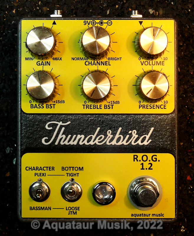
Being touted as a respectable Plexi emulator, I gave the R.O.G. Thunderbird (hereafter: TB) a shot (pun not intended). Due to the heritage it was obvious to try the Bassman resp. JTM-45 side of it, so I made a switchable Fender stack counterpart. In this process the Duncan Tone Stack Calculator (hereafter: TSC) proved to be an indispensable tool[1]. Back To Index A Look At The R.O.G. Schematic Before continuing,
you may want to study the original TB documentation[2]
from R.O.G.
I also strongly encourage you to look up the Rob Robinette article[3] to learn more about Marshall´s evolution of amps and their internals. We are referring to those later on. The emulator is based upon a Superlead 100 model, but they leave it uncertain, what has been customized about it. That said, the TB appears to be sonically geared towards what is colloquially known as a Plexi (two channels), with cool biasing. (see chapter on Warm / Cool / Cold Biasing) Before we start, a short (incomplete) model overview to clarify the nomenclature used:
Note however
that this classification is very coarse and cannot
be generalized, because the models have evolved
gradually.
So let´s look at the way the TB works. As the model it is created after, the TB utilizes distributed distortion:
We will look at those distortion generator sections individually. R.O.G.´s channel-morphing idea by the way is nothing short of genius.
Since the early tube stages are only there to bring the weak guitar signal up to useful levels, there is no distortion to be expected from them, although using both of them together would yield a higher signal. Consequently, mixing plus a gain control suffices. The first anti-parallel diode pair does not contribute to tone. It is there to limit excessive input signals to safe values very likely to prevent awful op-amp limiting further down the line. Back To Index Topology The second stage is their crafty dynamic-shift unit (see original text). This is comprised of a complex diode network of unequal diodes, destined to produce some asymmetric (even order) harmonic distortion dependent on playing dynamics.
Back To Index Warm / Cool / Cold Biasing Altering the working point (a.k.a. biasing) of the first lead channel valve is another key element for the later Marshalls´ (Superlead, Plexi) characteristic sound. The reference to temperature stems from power tubes, which really can be run cooler or hotter dependent on the bias. The hottest bias you can have in a single power stage tube is class-A (symmetrical excitation), the coolest is towards class-B (single lobe clipped). Note: do not confuse this with the power stage operation methods push-pull and single-ended.Where early Marshalls (and Bassmans) had a small (820 Ohms) cathode resistor, later models had 2.7k, eventually peaking in a 10k value for their JMP models, commonly termed warm bias, cool bias and cold bias respectively (other makers even used values beyond that). This will limit the signal swing differently and thus generate vastly different distortion spectra. We will attend to that soon. They mention that they have chosen to implement warm bias, so what is the option? I wrote to Brian Tremblay from R.O.G.:
I believe, since there is no standardization of terms, there is possibly a bit of confusion in the way they and others are using the terms warm and cold bias. Since they are referring to a Plexi, it will most certainly be (according to the three possibilities described above) cool bias (2.7k cathode resistor) at most, whereas cold bias would certainly relate to later JMP models (10k and bigger). See also the Rob Robinette article for more information on this.Indeed I did not hear much of a difference that would warrant an additional front panel toggle switch, but I did not investigate the subject deeply. So this may truly be a matter worth of deeper investigation. We may even be able to cross into JMP-land with the TB. Let us know if you find out more and I will add it here. Later models (JMP series) made use of the cold bias.
Back To Index Phase Inverter And Output Stage Distortion As the R.O.G. write-up says, the majority of distortion is generated in the phase inverter stage, and this is consequently realized in the TB´s late LED stage. That said, I do not buy their claim that power amp-like distortion is not symmetrical in push-pull amps. Agreed, it may not be perfect, but it will be for all practical purposes. But since this emulator (or any emulator FWIW) cannot possibly take into account rectifier type, tube type, output stage reactance, power supply stiffness or whatever, their decision will overall serve the purpose.
Note that Merlin
speaks of preamp stages at this point.
It is therefore crucial for an amp at which point it transits from asymmetrical to symmetrical. I had the impression the TB pretty early transits into power stage type distortion. A resistor in series with the 50k input resistor into the LED stage (such as another 50k for a total of 100k) introduces a little more attenuation for the subsequent op-amp stage and transfers the "workload" to the previous distortion generation stage. Since we only have to dominant distortion generation stages, one asymmetric followed by one symmetric, this "gain staging" inbetween can determine the balance between them. This is easy to play with if you wish. Back To Index The Bottom Switch
So far we have looked at the inventory, and my schematic has been identical. Let us now look at what I have changed. You will find my schematics of the Son of Thunderbird above and in the Reference section.[4] This add-on switch toggles from a typical tight Plexi (and later) bottom (forgive the pun) to a loose Fender (and JTM-45) bottom. Staring endlessly at the schematics for JTM-45s (and incidentally, Bassmans) and Plexis, I found that the major basic technical difference is an altered bass response in the first amplification stage (disregarding the tone stack for a moment). Translated to our circuit, this means an extended bass range in the TB´s stage #1 as well. JTM and Bassman are practically full-range amplifiers due to the full decoupling on tube stage #1 (big electrolytic on the cathode). This makes those amps sound very woolly, but ideal for early Hendrix work and blues. Plexis incorporate a highpass around 700 Hz by using a much smaller electrolytic. This makes tone slimmer and more articulate, better suited for rock music. The TB uses a 22n/10k highpass that complements just that. To recreate the JTM´s full range, a 220nF cap in parallel to the existing 22nF cap does exactly that. By toggling in this capacitor (C16) with a front panel switch you can instantly change the bass range from a JTM-45 (or Bassman) type flavor to something later down the line of models. Due to the massive bass overload (bass is containing more sound energy anyways...), most distortion appears in the lower register. This can produce some really useful vintage sounds, and an early bass control, such as on the guitar or an preceding EQ, or an altered setting of what R.O.G. calls "tone" (channel blend) can help to tame the distortion texture at will. And then we have a post-bass control too to balance the bass output. Back To Index The Character Switch This add-on switch toggles from a typical Marshall tonestack (Plexi and later) to a Fender (and JTM-45) tonestack. The JTM is nearly a clone of a Bassman, it has even (besides having a different power stage gain and feedback) a Fender type tone stack. Fenders are known to be comparably mid-deficient. Playing with the Duncan TSC I quickly found a suitable Fender equivalent to match the TB circuit. Note also that my main drawing is closely related to the original R.O.G. drawing. However it uses a 2x3 pin Header that connects to the optional switching board. If not used, it is jumpered to stock mode.In the TB´s tone-stack equivalent all resistors are chosen so that they emulate the controls on "max" position, except for the Fender emulation, where the treble section had to be dialed down with a fixed divider to mimic the classic Fender tonestack closely. How to use the Duncan TSC. Enabling the Fender stack without the full-range bottom end sounds mid-deficient and bass-deficient, as one would expect from a Fender, but with the full bass end, this sounds suspiciously like a Box-Of-Rock less the hiss (in lack of comparison with genuine tube devices), which claims to emulate a JTM-45. Again, like one would expect, this can easily be too woolly.
While plugging the
R.O.G. tonestack components into the Duncan TSC I
found that they do not match the stock Marshall
values too well, last but not least by an
impedance mismatch with the subsequent stage´s input
impedance. I accordingly tweaked the values slightly.
Note: the typical schematics shown at the TSC presume a tube amp environment, that has medium impedance drive and high impedance inputs, whereas in our solid-state environment we have low impedance drive and medium impedance inputs. Take that into account when trying other the settings. Accordingly, the values for stack components as used in solid-state circuits do not necessarily need to be high impedance. I tried a
full-bypass on the tone-stack switch at first, but
this just added complexity without useful
effect.
The Fender stack produces a massive "hole" in the spectrum where the ear is most sensitive and thus appears less loud than the Marshall stack. R3 on the switching board functions as an additional series resistor (if in "Plexi" mode) that together with R38 forms a total resistance of 150k into the subsequent op-amp stage (before: 47k), which drops the gain of this stage somewhat in order to compensate for the different perceived loudness factors. Back To Index Noise Considerations Although noise is not as bad as one would expect with that amount of gain (and much lower than, say, a Box of Rock´s MOSFETs), there is leeway for improvement. It is known that some op-amp devices are optimized for current noise and some for voltage noise, but the resulting noise performance has to take the surrounding environment into account. Looking at the complex circuit, it was not easy to determine for me which would perform better just from the top of my head, so I just tried. NE5532 performed well, but uses an astronomic supply current. Besides that, two of them blew in the LED stage upon an inadvertently loud input signal pop. So don´t try them there. An OPA2134 made the first stage´s noise appear less white, and the rest worked well with LM833. What further complicates the matter is the fact that I chose dual op-amps and shared the individual parts the way they were easing the layout. The best option from an op-amp-rolling perspective is of course single case units. All op-amps should be decoupled with a 100nF ceramic cap across the rails close to the IC package. I noticed that there are no current balancing resistors that are customary on circuits optimized for low noise on the reference voltage pins of some op-amps (say the LED section), so I added those, but they did not bring any improvement I could detect. A 68pF to 82pF MICA cap on the LED stage brings down this stages corner frequency to a level where noise performance appears improved (5k/4kHz). Back To Index Power Supply Section R.O.G. suggest tantalum caps for the charge pump for their low ESR values. The values needed were not available, but besides that tantalum are said to be very unreliable and I have seen not only one of them bursting in flames despite being treated well. I chose OSCON caps that use a polymer electrolyte to achieve even superior ESR performance. Although the ones that were available (Panasonic SVPF series) are surface mount and can normally only be soldered in a reflow system, they are just wired components with the leads tucked under. So if you remove the square plastic case on the bottom, its leads will stick out straight and you can solder it like on any through-hole radial cap. They are also made a through hole components named SEPx series with equally great performance.I have used them in previous projects for charge pumps. They work terrific. I would not use standard electrolytics, they are really not fit for such purposes due to their high ESR. Back To Index Verdict Due to the big
spread from clean to overdriven tones this is a very
versatile and convincing Plexi Marshall emulator.
I feel it is very dynamic and has a lot of the charm of what is generally associated with early Plexi tone. Together with the additional switches it can emulate a JTM-45 resp. Bassman too. If the extra effort pays, is debatable. They are indeed very close siblings. If you plan to ride the volume as them ole´ folks did it, a buffer will definitely improve your experience, or otherwise you may have terrible treble loss on dimed volume settings. Read my suggestions in an article dedicated to that[5] . It stacks very well with other units, which is by far not common with all such units. It has undeniable hiss, but not too bad, and certainly much less than some stacked FET or MOSFET competitors I have. Bear in mind how noisy a real amp at full throttle would probably be. That said, I use an external 4-wire noise gate, which successfully eliminates the noise without stifling the dynamics. THAT´s the penalty (THAT 4301 to be exact). The output frequency shaping is very useful and effective, although I sometimes wish I could tone the treble range further down. I increased the presence cap (C35) to 4.7nF which works better without adverse affect. With the Bassman extension cap on "full range" you have a lot of bass, which can be dialed out with the output bass control. Together with a pre-bass control ( e.g. on the guitar) you have a myriad of bluesy and early Hendrix rock tones and textures available that are typically associated with JTM´s and Bassmans. Both toggles up reflect the stock TB tone, but both down yield a JTM-45 (=Bassman) tone. You can also have intermediate settings, like a Plexi stack with a loose bottom, which is probably non-existant in real life. All positions are eminently usable, although (as expected) the difference in available distortion textures is not enormous. You also won´t just switch from one position to the next (particularly the fullrange bass position which is equivalent to a boost) without changing at least the post-bass control and / or the guitar´s bass cut or the channel morphing control ('tone'). We are effectively changing amps... If I were to eliminate one of the switches, it would be the stack changing switch. The bottom switch really does something and is really easy to incorporate into existing designs... The Son of Thunderbird can be built upon any existing PCB with the addition of an external switching board and some wiring with minimal intrusion. I have added the time constants (resp. cross-over frequencies) to help relate to the original tube amp drawings, where it is easier to see. Also the expected voltage values after each subsequent gain stage. The main schematic as shown is practically equivalent to the original R.O.G. schematic except for the additional header. Deviations from that are marked. Note that the op-amp designators in my schematic do not relate to the original drawing. All external switching circuitry (character switch and bottom switch) resides on an optional external board, which makes it easy to evaluate. Back To Index [1] Duncan Tone Stack Calculator: http://www.duncanamps.com/tsc/ [2] R.O.G. Thunderbird, http://www.runoffgroove.com/thunderbird.html [3] Rob Robinette: How the Marshall Plexi, 2204 and JCM800 Amplifiers Work, https://robrobinette.com/How_the_Marshall_JCM800_Works.htm [4] Son of Thunderbird schematics: Main board (basic TB), switch board (option) [5] Aquataur Electronik: A Sonic Wrapper Around A Vintage Pedal [6] Merlin Blencowe, Designing Tube Preamps For Guitar And Bass (2nd Ed.) Back To Index Update History
MAIN PAGE>MUSIC STUFF>SON_OF_TB |
|||||||||||||||||||||||||||||||||||||||
| MAIN PAGE | MUSIC STUFF | IMPRESSUM (c) 2022-25 AQUATAUR Musik & Elektronik |