|
Colorsound
Dipthonizer™ - LM13700 fueled This rare but underestimated circuit adapted for LM13x00 OTA´s, with extensions for Expression Pedal control and S/H á la FSH-1 last update: Nov 22, 2014 Copyright 2014-26
by H. Gragger. All Rights Reserved. All
information provided herein is destined for
educational and D.I.Y. purposes only. Commercial
re-sale, distribution or usage of artwork
without explicit written permission of the
author is strictly prohibited. The original
units with their associated
trade-names are subject to the copyright of the
individual copyright or trademark owner. The
Author is by no means affiliated with any of
those companies. References to trade names are
made for educational purposes only. By reading
the information provided here you agree to the Terms
of
Use. The
working language is kept in English as an aid. Read
here
why.
|
||||||||||||||||||
| MAIN PAGE>MUSIC
STUFF>DIPTHONIZER13x00 Index
Abstract This is an in-depth analysis of the Colorsound dipthonizer™ circuit (ore honeydripper as described by Madbean). The original (?)
schematic is available on the web, which appears
to be the template
for Madbean´s
rendering – nearly a 1:1 copy including
some
components that of are questionable value and of
course the venerable, but
obsolete CA3080. Purpose of this exercise is to replace the CA3080 by the current-production LM13700 OTA (operational transconductance amplifier). Since any modification of a circuit requires a thorough understanding, the schematic has been processed and redrawn so that functional blocks become obvious. Most commercial schematics are not drawn this way. Finally, the transition to the LM13x00 has been made with surprising little change. The insight gained with this project
will help for future projects
that may require an LM13x00 to replace a CA3080
or indeed to tweak
any circuit that contains an OTA.
Back To Index Introduction
The Colorsound Dipthonizer™ is a stompbox effect no longer produced. It consists of an envelope processor to control formant filters which produces dipththong-like sounds. It is functionally similar to the widely-known auto-wah device, but produces a much more pronounced vocal effect. It strongly resembles the effect of a „talk-box“, which uses the mouth cavity to produce those effects. Madbean was kind enough to resurrect this long-lost effect and update it to a contemporary power supply, however he did not try to update the long obsoleted CA3080 transconductance amplifier to something in current production, such as the LM13700. Madbean has updated the power supply section to contemporary usage. It was not quite clear whether a 1:1
change was possible. In order to answer that, a
thorough
understanding of the circuit was necessary. The
outcome of this is presented in the following
document. All
designators refer to the Madbean
schematic
Rev. 1-a 12-11, although the original schematic
is identical except for the added power supply
components. Output resistor R18 has been
increased to the more common 2k2 with no audible
side effect. In the Author´s schematic, many subcircuits have been rearranged visually to make their function more obvious. Although functionally equivalent, the readability of a schematic circuit is vastly dependent on consistent repetition of similar function blocks in a shape the reader is used to. This is known as pattern recognition.
As customary for good quality PCB design, local
decoupling caps have
been added to all IC packages. With respect to
those preceding me, who have done a lot of work
and maybe want to make a living out of selling
their PCB´s, no PCB per se is being presented in
this place.
Back To Index Front-End (This would be a great
time to produce a printout of the schematic.)
Extensions: Sample and Hold
Mode á la
FSH-1 and BeyondThe first thing that meets the eye is a pretty low input impedance. 100K is not considered high, a 1Meg would be more appropriate without penalty. Also, there is no RF filtering provided. Any proper input circuit should limit the bandwidth of incoming signals to the frequencies of interest, but sometimes those decisions are not governed by ratio, but by the buck. In the Author´s rendering of the schematic a simple RF input filter has been included. IC1B is a roughly x2 inverting amplifier which biases around +5V. The voltages in this circuit appear very carefully chosen to optimize the envelope functions. IC1A is a conventional inverter with huge gain, whose output is limited with two diodes. A non spectacular diode clipper which is not meant to sound particularly pretty, but to produce harmonics galore. Both outputs are summed over a “fuzz” pot that allows to blend from a clean tone to a harmonically enriched tone. Gains are matched so that there is no apparent volume step in sweeping the pot. (Note that in V1.1 of the schematic the fuzz pot is rewired in reverse to inflict a sense of "more" clockwise on a pot named "fuzz"). Madbean uses an LM324 which is not particularly low noise. A low noise quad amp may be beneficial for the input stage(s) at the cost of supply current, although this is entirely irrelevant for the envelope (IC´s 1C-1D). An TL084 has been used for subjective improvement. From the clean stage IC1B the sidechain (CV - control voltage) signal is derived via the attenuation pot termed “sweep”. (Note that since the sweep pot does nothing for 3/4 of its working range, it has been replaced by a 8.2k fixed resistor in conjunction with a 2kB pot, which increases the usable mechanical range to its full sweep. A 2.5k pot and a smaller fixed resistor might work even better but was not at hand.) Back To Index Envelope Generation IC1C is a conventional precision half wave rectifier[1] with the diodes put the way that a positive signal will produce a negative envelope (mirrored around the 5V reference) that exactly complements the signal above the reference voltage. C12 will provide some rather long time constant to filter out high frequencies. Its gain is fairly high by the choice of R20/R19. Via LP filter R21/C13 this signal is wired to the rotary switch SW1A, a mirror image thereof (mirrored around the 5V reference, thus a mirror image of the envelope around 5V) is produced with IC1D. (Note that this latter is NOT equivalent to the real lower half of the envelope, but will be a close approximation. The choice is inconsequential). The circuit around IC5B is almost identical to IC1C except for a higher filter time constant. Its gain is one for R28/R26, but provides a second path through R28/R27 and C14, which introduces a volume boost for treble. The choice of the two time constants (long first, short later) appears to be chosen carefully to produce a useful envelope. Since a precision half wave rectifier of the sort used is an inverting amplifier at its core, it can be used to sum up voltages. Indeed the second half of the rotary switch connects different resistors to the “reference summing point” at the non-inverting input (R24 and R25 resp.) which, add a varying DC offset to the envelope signal dependent on their ratio to R28. Since all HF content is pretty much gone already, this circuit block is more appropriately termed “impulse shaper and level shifter”. IC5A is just a buffer that drives the biasing input of formant2 (around IC3 and IC4B). There is something not clear about the circuitry surrounding this block. IC5A is just a +1 buffer with full feedback. The capacitor on its output (C16) does not make any sense. In the contrary, every designer is trying to avoid having to drive a large capacity with an operational amplifier, since this may lead to oscillation and OPA overload[2]. Also, the function of R30 is unclear. IC5B will maintain a DC level on its output regardless of any load to a supply rail so no "pulling" resistor is necessary. IC5C again is a function block similar to IC5B, although, caused by the direction of the diodes, it favors the negative envelope. This one is referenced to about 2.5V, which is provided by the R34/R35 voltage divider in the power conditioning section. IC5D is a summing amplifier adding up the signals before and after IC5C in a defined ratio. The network around R40/D9-11 clamps its output to 3*0.7V and feeds formant 2 through R41 (signal called "ENV-1"). Formant 1 is driven by the output of U5a ("ENV-2"). Back To Index Formant Filters
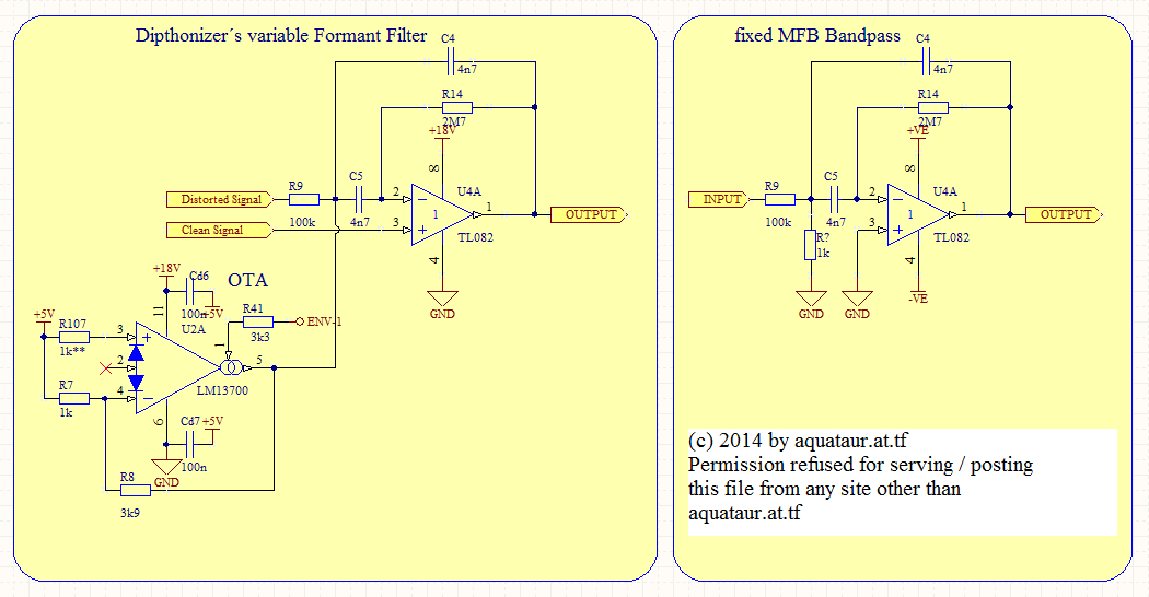
IC4A and IC4B are MFB Bandpass filters[3],[4],[5], whose center frequencies are swept by a transconductance amplifier in front of them (IC2, IC3 in the original design). The way formants work is explained here:[6], [7] The formant filter used is basically a high-Q bandpass similar to the one shown here:[4]
The resistor on the input of such a generic filter that goes to ground is replaced by the output impedance of the OTA (or rather the varying current thereof), which sweeps the frequencies. The frequencies and ranges themselves appear very well honed by the original designer to make for a good vocal quality. Note that the non-inverting input of our formant filter does, as different to the MFB filter shown in the link above, do not go to a center rail (ground in this instance, +5V in our instance) but rather to the “clean” input signal derived from the input buffer. A distorted, harmonically enriched signal is the one that actually goes through the filter. The output will provide a mixture of the two. Both filters are mixed together by a hard-and-fast summing node comprised of resistors R15 and R17. The designers have saved on an summing amplifier there, but it seems to work. Back To Index OTA´s (Operational Transconductance Amplifier) The OTA is run with a closed loop (negative feedback through R8 resp. R11) which makes the output current independent of supply voltages and solely related to bias current. The output sees a 1K load, since the closed loop gain is 3.9 and the feedback resistor is a 3k9. Since there is no additional load, any output voltage must develop across this resistor. The inputs are tied to a reference voltage (5V), current into the inputs is limited by R7/R10. (Noteworthy is the fact, that the non-inverting inputs don´t have a current limiting resistor, which all application notes advise against. [8],[9],[10]). A resistor of equal magnitude as on the inverting inputs has thus been inserted in the Author´s version of the circuit. Back To Index CA3080 vs. LM13x00 In the LM13x00[11] linearization diodes are implemented. Those help to lessen any non-linear distortion of the input signal on the non-straight B-E curve of the input transistors. The CA3080 does not have such diodes[8], however, since the inputs are both at the relative same level, no input distortion is to be expected and therefore those pins can be ignored if using the LM13x00. Thus, from their architecture, the only other relevant difference in their essence between the two chips is in the additional diode in the bias current mirror. Since the control sweep of the OTA´s is in our case directly proportional to the bias currents, equal current schemes have to be maintained. This is most easily accomplished by raising the relevant (envelope) voltages by a diode drop, which in turn just requires the “center” voltage (about 5V) to be raised by a diode drop. Of course, the bounding circuit around Diodes D9-D11 has to rise a diode drop too. By those simple measures all control voltages are risen by a level that guarantees the same bias currents and thus filter sweeps. The LM13x00 package also contains an output buffers per OTA, which can be left uncommitted. So, yes, the dipthonizer can be driven with LM13x00 IC´s with only minor changes on existing boards that use CA3080. Since the LM13700 and LM13600 only differ by a detail that affects the output buffer (which is unused and uncommitted in our application), both of them can be used. Back To Index Power Supply And Fault Protection Madbean leaves the Vout pin of the LT1054,[12] (pin 5 on the 8 pin package) open, it should be grounded according to the datasheet. The protective Zener diode on its input is of somewhat questionable usefulness. Although for reverse powering a ¼ Watt diode may be sufficient to withstand a reverse current surge, it is certainly underrated for excess overvoltage. With more that 30mA power consumption the circuit calls for a mains-derived power supply, but because fresh batteries have voltages well in excess of 9V, trying to power the circuit with a 9V block battery will invariably cause the Zener diode to conduct. Thus a Zener diode beyond 9.8 V with a 3W rating appears in place. The LT1054 can take voltages up to 15V safely. A 3W Zener will limit a 300mA current safely. The Author added a small resistor in series with the battery input that helps to protect D12 from overcurrent. Don´t overdo it with that, since there will be some voltage dropped across it during normal operation. To further lessen any HF injection from the PSU, a small coil has been introduced. In practice there will be no double voltage. With the topology given, some 15.5 Volts appear on the output. Output voltage will be VOUT = 2VIN – (VL + 2VDIODE), where VL = the LT1054´s voltage drop (current dependent). Using shottky diodes improves this to about 16.8 Volts. In a battery (or other low voltage) driven environment no Volt can be afforded to be wasted. The circuit runs more pronounced with this improvement in place and uses less supply current (34 to 26 mA). This is indicative for lower internal loss and a good thing. Back To Index Practical Experience and Verification Since the author does by no means claim perfection, the above design considerations for using the LM13x00 had to be verified empirically. Indeed the substitute works like a charm with the diode lifts in place. Lacking an original CA3080 equipped circuit, no 1:1 comparisons can be made. However the board sounds convincing with very usable envelope range. To verify the diode lift thesis, the extra diodes D112 and D117 have been temporarily shorted (which will be equivalent to the original circuit). The circuit still does something, albeit obviously with a wrong working point. Alternatively, the current setting resistors into the OTA´s R41 and R31 might be tweaked proportionally. Also, the current limiting resistors R107 and R110 into the OTA´s, as demanded by the datasheet, don´t get in the way. The distortion section´s effect is rather mild, barely noticeable, so the Author suggests to do Madbean´s modification and use a much smaller capacitor in this position. A 680pF Styroflex was used with pleasing results. The components of questionable purpose, C16 and R30, were omitted without sonic impact. No destabilization was to be expected or was observed. Back To Index Extensions: Expression Pedal Mode Although not part of the original design, the idea of installing a pot for manual, or rather, foot controlled usage, is obvious. It originally stemmed from a forum user that calls himself “Ronan” on DIYstompboxes:
Full credit to Ronan for this idea. In the Author´s stompbox housing a TRS (see below) jack is installed, where on the ring ("send") a fixed voltage is presented to a stock high-impedance volume pedal, and on the tip ("return") DC level returns that is proportional to the pedal position, which gets connected to the "mode2" pin when the external pedal ist plugged in. When unplugged, "mode1" and "mode2" pins are connected ("auto" mode). Look at the schematic for more details. A 500k trim pot is installed in series with the external (volume pedal) pot on the top and bottom leg respectively, that sets the action range for the expression pedal, because some voltage ranges are unusable. Note that in case dipthonizer´s and the volume pedal´s (metal) enclosures touch, the bottom trim pot will be defeated. Both trim pots are somewhat interactive. +5V as reference voltage was found to give the best usable voltage range, where +10V would give an exaggerated top end with reduced useful bottom range. A series current limiting resistor Rcl prevents excessive current draw on the +5V supply if the top trim pot is set to minimum and by accident a mono jack is inserted in the TRS connector, which would short the ring to ground. The Author uses a stereo jack with switching capability as an interface to an external TRS jack (tip-ring-sleeve) as shown here. The EXP pedal activates as soon as it is plugged into the EXP jack. A stock TRS cable connects to either a TRS expression pedal, or a stock volume pedal, which works with possible functional restrictions:
Note: the nomenclature for sleeve and ring on the 1907 drawing of the "triple contact plug" displayed there differs from today´s usage. Using such a volume pedal, the taper did not seem a problem once the upper and lower trim pots were set to taste. The EXP pedal works similar to a wah pedal in that it cuts highs the farer back (heel down) the pedal is, however its tone has a far more "vocal" quality. The expression pedal allows to use all modes at once, while auto mode is restricted to only one mode dependent on the switch setting, which makes it even more vocal. Since this mod comes into the bargain and works really great, it is a keeper. Back To Index Due to the striking similarity to the Maestro FSH-1, (or as Madbean puts it, the Sharkfin), it was obvious to try the random section (or sample and hold) the FSH-1 has. Although working, the sonic results were inferior. Diphthongs don´t sound well if scrambled that way. This produces a bubbling effect not very musical, the application is thus not pursued any longer. Read more in my FSH1 document. However, the externally available CV input may be linked to more fancy CV generators, such as a sinusoidal wave. While the usability of this may be subject of discussion, Digitech have made an effect exactly like this (Auto-Ya-Ya). Back To Index Reference [1] National Semiconductor Linear Brief 8 (LB-8): Precision AC/DC Converters [2] Microchip Technology Inc AN-884: Driving Capacitive Loads With Op Amps [3] Active Filters - Characteristics, Topologies and Examples: http://sound.westhost.com [4] Multiple Feedback Bandpass Filter: http://sound.westhost.com/project63.htm. [5] Multiple Feedback Band-pass Filter Design Tool: http://sim.okawa-denshi.jp/en/OPtazyuBakeisan.htm [6] Human Voices and the Wah Pedal: http://www.geofex.com/Article_Folders/wahpedl/voicewah.htm [7] Synth Secrets, Part 23: Formant Synthesis: http://www.soundonsound.com/sos/mar01/articles/synthsec.asp [8] CA3080 datasheet, Intersil [9] Nuts and Volts magazine, Ray Marston, Understanding And Using ‘OTA’ Op-Amp ICs parts 1 and 2 [10] Radio-Electronics, Ray Marston, Working with OTA´s [11] LM13700 datasheet, Texas Instruments [12] LT1054 Datasheet, Linear Technology: Back To Index Update History
MAIN PAGE>MUSIC STUFF>DIPTHONIZER13x00 |
||||||||||||||||||
| MAIN PAGE
| MUSIC STUFF | IMPRESSUM (c) 2014-26 AQUATAUR Musik & Elektronik |