|
Digesting
the
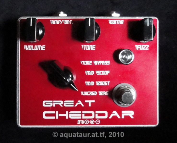
Great Cheddar How to make the Big Cheese most tasty last update: May 14 2010 Copyright
2010-26 by H.
Gragger. All Rights Reserved. All information
provided herein is
destined for educational and D.I.Y. purposes only.
Commercial re-sale,
distribution or usage of artwork without explicit
written permission of
the author is strictly prohibited.The original
units with
their
associated trade-names are subject to the
copyright
of the individual copyright owner. The Author is
by no means affiliated
with any of those companies. References to trade
names are made for
educational purposes only. By reading the
information provided here you
agree to the Terms
of
Use. The working
language is kept in English as an aid. Read here
why.
|
||||||
| MAIN PAGE>MUSIC
STUFF>GREAT CHEDDAR Index
A Unique Challenge Building this fuzz box was not a challenge for me in the usual way. The circuit topology is thought about very well, there are no impedance matching issues (input impedance is high, output impedance low), no sag switches, no mojo transistor issues, no tone control mods, nothing. It sounds very good (matter of taste of course) as is. No, this device was a mechanical challenge. R.G. has made a pretty layout which, although a bit crammed for my taste, works very well. The crunchpoint is, that the PCB is directly attached to the rotary switch and thus holds in place just by the switch mount. Cramming this inside a BB box together with all the other mechanical parts took me quite a few hours of component rochade, but this worked out beautifully. R.G. mentions in his document that some components might need tweaking. Reading the threads in the D.I.Y. fora, this seems to be confirmed: Back To Index Setting The Bias And The Intentional Mis-Bias Upon first turn-on all the settings sounded very gated, the forth position (what I preferred to call "wicked bias" or what the Big Cheese calls it: "swiss") was almost no sound except a few farts. Some builders have mentioned that their fuzz box does always sound sputtery, independent of the switch position, just like mine. I immediately suspected mis-bias and I was right. R.G. measures the voltages on the two transistor stages, I had about the values given on the first stage, but a collector bias of 1.5 Volts on Q2 with the given 10k collector resistor. This is most certainly too low with the given transistor (BC237) compared to the 2.8V R.G. recommends. Logic dictates that the collector potential rises with a smaller collector resistor. Mind: this adjustment has to be done in pos. 1-3, because 4 is a different issue as will be explained soon. Of course the emitter resistor will have some influence as well, lowering this will increase the stage gain and the current, but will also limit the headroom. From a higher frequency perspective this happens with the fuzz control, which gradually bypasses (for AC purposes only) the emitter resistor. There is provision been made in pos. 4 ("swiss") to deliberately shift the bias setting of transistor 2 into the cut-off region, which somehow interacts with the settings of the fuzz pot. I removed Q2´s collector resistor R8 (10k) and replaced this temporarily by a 10 k pot. It turned out that raising Q2´s collector to some 4V (by decreasing R8) will make the overall sound much clearer in pos. 1-3. The recommended 2.8V made for a fairly mushy sound in pos. 1-3 and a very gated sound in pos. 4. I decided that a mushy sound in all positions would defeat the entire purpose of the rotary switch, so I opted for a cleaner sound in pos 1-3 and a pretty gated sound in pos. 4. The on-board trimmer P1 is only active in pos. 4, and the bias there measures then about 2 Volts. The gated tone changes with the fuzz pot setting, although not much. It just disappears when the fuzz setting is too low. A balance has to be stricken for the setting of R8 and P1, so that the gating effect does not get useless when the fuzz pot is fully up. I chose to set R8 in a way so that in pos. 4 I have a pretty gated sound with the fuzz pot slightly taken back, so there will be some tone margin on the fuzz pot setting. P1 is set to mid-ways, leaving some margin for adjusting the mis-bias to taste. R8 turned out slightly above 6kOhms for the BC237 used.
I have no idea what he meant, but a hopelessly low biased Q2 will not produce more than farting, which will certainly not be close to the original. With some transistors this may work out-of-the-box, but if it doesn´t, tweak R8. By the way, I used a very low gain 2N2969A from my Poker Face just for the crack, and this did not alter the tone dramatically. I postulate that this fuzz is not very device sensitive. This is a crude cheese crust, not a fuzz face. In my mood for modding I also tried to replace the funny diode-connected transistor by two series connected germanium diodes, and this took away some of the nice dirty grit this box makes out. After two seconds the transistor was back in place. I also removed the series diode that protects the circuit from inadvertent reverse battery connection and replaced it by a 56 Ohm resistor. This then works as a low pass filter to clean up a badly regulated wall wart supply. I installed a GEO polarity protection instead. I did not use the millennium switching circuitry as depicted, because a 3P2T footswitch is hardly more expensive and delivers a better result. This has become almost standard in contemporary bypass switching circuits. Back To Index Sound Samples A few basic sound samples can be found in the stompbox gallery. More to come. Back To Index Update history
|
||||||
| MAIN PAGE
| MUSIC STUFF | IMPRESSUM (c) 2010-26 AQUATAUR Musik & Elektronik |