|
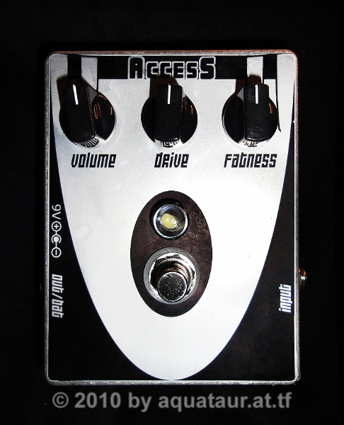
The ACCESS
Fuzz a.k.a. AXIS
Fuzz Biasing And Tricks For "Stage Tone" last update: Apr 28, 2022 Copyright 2020-25 by
H. Gragger. All Rights Reserved. All information
provided herein is destined for educational and
D.I.Y. purposes only. Commercial re-sale,
distribution or usage of artwork without explicit
written permission of the author is strictly
prohibited.The original units with their
associated trade-names are subject to the
copyright of the individual copyright owner. The
Author is by no means affiliated with any of those
companies. References to trade names are made for
educational purposes only.By reading the
information provided here you agree to the Terms
of
Use. The working language
is kept in English as an aid. Read here
why.
|
||||
| MAIN PAGE>MUSIC STUFF>ACCESSFUZZ Index
Foreword To The 2024 Update This unit comes up in magazines and musician's forae again and again, being touted as the holy grail for Hendrix Tone. The circuit is well known and primitive to make, however I never got to sound it to my like. Hearing customs change over time. Over the years I gained some humble mastership in biasing a Fuzz Face correctly (and by this I am of one mind with Björn Juhl in that it should be biased to clip symmetrically), but I never got the Axis Fuzz to bias this way. It always clips the top lobes heavily, while the bottom lobes go unharmed. Some may like it this way, but I do not. Unfortunately, this thing has nothing in common with a Fuzz Face technically, so all biasing measures borrowed from that failed catastrophically. Frustrated by this, I bit the bullet and analyzed the schematic. There are a few things that turned out that I have seen being addressed elsewhere. I add the update towards the end of this writing. Be prepared that some judgements made years ago are downright contradictive to the current insights. I decided to leave that as is for clearance. Back To Index The Decade Of The Sleeping Beauty
I have built this circuit more than a
decade ago and found it to be very sputtery and
farting. The second transistor always seemed biased
way too high so that there was never a clear signal
coming through. Despite all transistor swapping I
never seemed to get this one working. I was already
considering re-using the aluminium case for another
project.
It was lying dormant for over a decade (look at the time stamp on the picture), but recently I saw videos of guys using it and was intrigued again. I finally got it working and found some tricks that really make it shine, which I am glad to share with you. The Axis Fuzz does not have the typical woolly Fuzz Face rasp, it is rather screaming. It has something which I only by exaggeration managed to identify as spurious octave effect, which in small doses adds what makes this unit special. The term "fuzz" is actually misleading by today´s nomenclature, since it suggests a typical Fuzz Face architecture, which it has not. Both nevertheless have a lot of sonic territory in common. More than any fuzz I have it is a unit that goes ultimately clean at low guitar volume settings, but it gets beautifully raucous with picking dynamics. This unit is heavily geared towards treble boost to counteract some problems that no longer exist, so unaltered, it were for my purposes virtually unusable. Luckily, those problems were very easy to solve. It has become my new favorite fuzz unit - for a while... Back To Index Jimi´s Legacy (Or Spell) It is fact (R.M. himself has
said that) that there have been constant
modifications to the devices sculpting Jimi´s
tone.
Back To
IndexDespite the reduced technical potential of the time, he may still have used HP and LP filters and buffers as needed in the studio, even if it may just have been a cable with high capacity for that high-cut or a different capacitor on the input to cut bass that went without mention. We do not know what was buffered, why some of his Fuzzes worked "the impossible way" before or after a wah and so on. R.M. surely did not have any preconceptions about things if they worked, however you can rest assured that he does not reveal all tricks. This kind of secretive policy is starting to make me tired, particularly if it is used to fuel hype and sales numbers at the expense of the customer. On the end of the day, we have to state we do not know what was inside those cast-iron shells. I thus strongly encourage the kind reader to experiment with those things free of prejudice and dogma. Hendrix by the way was one who was highly unorthodox musically and technically. Listening to the recordings over time it can be taken for granted that there has been some change in the fuzz tone´s timbre. I do not hear the wholly tone of germanium on later recordings, which coincides with what is being spread - a change to silicon, de facto meaning a change to the Axis Fuzz. I can feel that. I think we can safely agree that R.M. understood that all Fuzz Faces suffer from low input impedance, and that he knew how to remedy that. We can thus further conclude that the wah into Fuzz Face problem can be (and has obviously been) solved (by simple measures) and obviously without ruining tone; visual and tonal evidence clearly documents that. So this alone would not be a reason for people to adhere to vintage at all cost. In fact it astounds me to see how many people still fall for the age-old Fuzz Face conundrum after so many years of technical elucidation.Nobody ever mentions that a musician / technician of that time permanently had to fight diverse technical circumstances and that devices like the Axis Fuzz (that already were an evolution of predating effects) had to compensate for. If you use such devices in a contemporary rig (that is no longer plagued by those shortcomings), unaware of the origins of those properties, then you will inevitable end up with a tone that is unrelated to what you expect.
Stage Sound - In Bedroom Studios? Vintage fuzzes generally benefit from some l.f. tailoring, it thus comes in handy that I have a bass cut switch on the guitar. Fuzzes clean up tremendously if the bass into them is restricted. Indeed I do not hear a lot of l.f. content in Hendrix´ guitar recordings. Those myriads of pedals may sound suspiciously like Grandmaster Jimi´s tone but they have to be used with a simulator that emulates a cooking tube amp if used in conjunction with an amp that is running fairly clean and at bedroom levels. In all instances you have to balance the high end somehow, and be sure, this was addressed back then and you have to address that too. One of the most famous pitfalls is the fact, that you want to hear the full (bass) range predominantly if you are playing alone to avoid thin tone. The ear´s hearing curve at low sound pressure is part of the problem. When playing in a band context, bass quickly gets in the way, so mid range boosters have been invented for a reason. Bass content early in the line of effects is a different beast, because it overloads the distortion units. Besides that, overdrives tend to create artificial sub-harmonics that enhance bass anyway. Keep that in mind before reaching for any early dial to bring up bass. However, you may make up for this on the amp to your heart´s content. People complain that their fuzz sounds flat horrible into their rig. Yes it will if you have a bright amp tone to begin with. Early full range (tube) amps were pretty dark sounding before subsequent models were voiced to current taste. And those amps were running full throttle, introducing additional sound shaping effects like distortion and compression. One thing we must not forget is cables. Those used to have a horrendous (by today's standards anyway) capacity which killed all treble flat. Hence the urge to regain treble by applying treble boosts. Both Fuzz Face and Axis Fuzz (momentarily disregarding misbiased units) have been found to sound lousy in certain configurations, and yes, this is down to the before mentioned facts to a great extent. Several musician's forae are full of complaints that the Axis Fuzz sounds unbearably shrill unless followed by a cooking tube amp that masks all it. This all is totally avoidable. Later versions of the R.M. effects (Voodoo series) have undergone some improvements that address those problems partially. We will look at that later and resolve the rest in a wash... Back To Index Experience With The Axis Fuzz I made a few general observations with my unit that I want to share with you:
Biasing This circuit is all about biasing, while being less touchy than a fuzz face (where everything interacts with everything). I had to work myself through a heap of forum threads to find the answer. This is a shortcut for you. Several sources (re-) quote that an original unit measures the following voltages (Vbat= 9.15V) 2N3906 2N3904Original hfe values are (allegedly) around 200. Use with discretion. I started out with the following transistors: Q1= 2N3906, hfe = 170All voltage readings were way out. The unit sounded horrible. According to the recommendations (see links at the bottom) I tried the following:
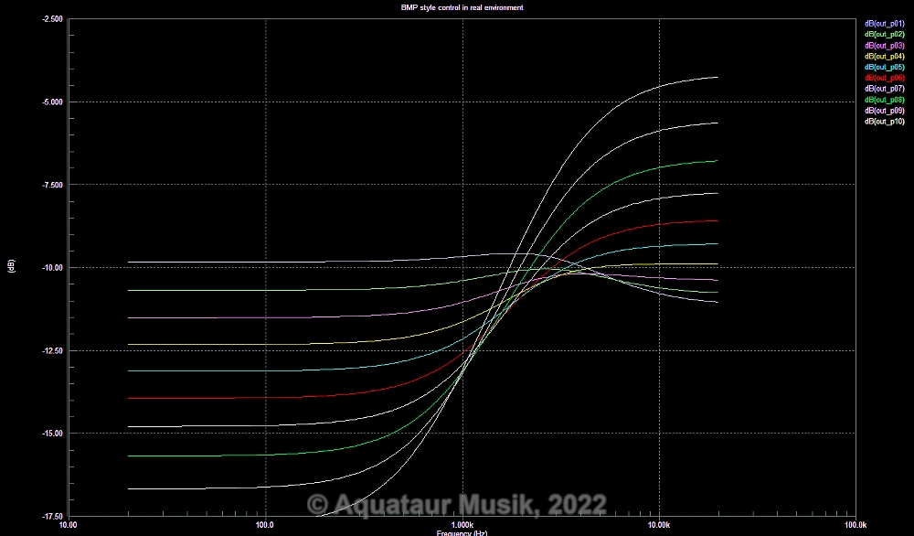
Back To Index Worthwhile Additions As mentioned above, the Axis Fuzz is geared towards treble boost. R.M. lateron elegantly introduced some adjustability by adding a BMP (Big Muff Pi) style tone control onto his Voodoo series (amongst other small features I do not consider essential). He calls the knob Fatness. The values applied in those units are comparable to the ones used in the Page-1 unit (see Reference), which lets us safely assume that they are used in all Voodoo series pedals.
As you see, on the maximum bass setting there is little damping to treble. Accordingly, tone gets "fatter" towards the bass side, without sacrificing treble, hence the name fatness control. According to the yin-yang of tone an increase of bass is perceived as a decrease of treble. Again we see R.M.'s attempt to fight against treble sucking. As mentioned earlier, I have removed the 100nF cap in parallel to the drive pot, which is a treble booster par excellance. With this BMP style control you have about unity gain when the knob is at 9 o'clock (trace #2-3). We can see that there is little treble damping above. Also, the "pivot point" is pretty high compared to a conventional BMP. This al is deliberately chosen so by R.M. We could revert the tonestack to a more conventional BMP stack style, even without the mid-scoop (see amzfx in the Reference section), but a BMP stack is always just a yin-yang to an extent. For my taste treble is still a bit high compared to my other effects. A 2.2 nF cap in parallel to the feedback resistor (22 k) makes a treble roll-off at 3.3 kHz, which seems to complement the fatness control nicely. Unfortunately, this type of control was not invented before some decades after Hendrix, it may have helped them to save a lot of grief. It is very effective and simple. It simply inserts between the output cap and the volume control, so it is an easy, inexpensive and rewarding retrofit to existing units. Back To Index 2024 Update: Circuit Analysis Note:
Input biasing network Folks have been wondering if the stacked resistors R3 and R6 (180k and 820k) can be replaced by a 1M. Read on. For DC purposes (and that's what we are concerned of for setting the bias), VCC and GND (via Cv3) are low impedance rails. No DC current will pass the electrolytic, so for DC it is of no concern. The two resistors can be treated like a 1M. The voltage set by this divider (assumed a perfect 9V supply) will be 3.6V. For calculating the input impedance (disregarding T1's influence) however we are concerned about AC, so the junction of Cv3 and R6 is a zero impedance node. Input impedance thus calculates by paralleling R6 and R8 to 370k. By yesteryear's standards a high impedance. So again, what are the electrolytic and the split resistor good for? For quietening the bias node voltage. Keep in mind that this was designed in an era where every engineer had grown up with valve circuits. In those, every preceding stage required some additional power supply (R/C) filtering to avoid low-frequency oscillations (motor-boating). Bingo. That's what this is: a filter for the DC used for biasing. Throughout the course of this analysis we will see that this circuit resembles a lot a non-inverting OPA stage as is state of the art today. Bias is usually set at half-supply - and filtered heavily! First Transistor Stage T1 gain is dominated by the emitter and collector resistors R4 and R9. Gain thus calculates by their ratio R9/R4=450. This of course is wishful thinking because the (vintage) transistor can never live up to that, but it will try. T1 (a PNP) in order to run will need a positive potential on the emitter and a negative one the collector. You may have to stretch your imagination a little, because you may be used to looking at NPN circuits. First, we look at steady conditions. Let's assume the drive pot (R1) be zero (=low gain). Cv3 is grounded and thus Cc1 with it. The output feed back resistor R7 conveys a potential that after the R7/Cv3 low pass contains nothing but DC. The node is called "TP1" in the schematic. We can now assess the voltages around T1. The base is set to 3.6V as determined above. The emitter (if T1 is turned on fully) will be some 0.7V different. In this case at 4.3V. We can assess the load current by applying Ohm's law to R9 - ca. 50µA. This is so low that it is to be bedoubted that T1 is turned on fully, but let's assume. We can only estimate its collector potential. For a fully turned on small signal transistor we can expect Vce,sat (collector-emitter saturation voltage) to be around 0.1V, but measurements show a 200mV difference. The collector thus resides at 3.8V. R4 provides some local feedback and at TP1 we may expect practically the same voltage as at the emitter. Let's assume a small voltage drop of 0.1V and TP1 will be at 4.4V. Second Transistor Stage (Ignore the pesky R/C combination at the base of T2 for the moment. We will come back to that later. It is of no concern to DC conditions anyway.) T2's base is at T1 collector potential: 3.8V. We can expect the emitter (provided T2 is turned on fully) to be at 3.1V. That said, measurements show that it is not turned on fully. The emitter resides at 3.3V. Likewise, Vce,sat for this transistor will be larger than expected too. Measurement tells us that it idles at 5.1V. Emitter- and Collector resistors are fairly large for a contemporary taste, and accordingly the current will be very small. I do not know why the design criteria were chosen this way. Collector resistors R2 and R5 can be treated as one as far as a collector load goes. They are split only to achieve a fixed volume reduction to provide sensical voltage values to the volume pot. This was quite common for those circuits. So the amplification factor we can expect is roughly 32k/39k. This would even amount to a small attentuation, but close to unity. However, R10 (the emitter resistor) is fully bypassed, so T2 will try to amplify as much as its hfe allows for. The voltage variation on T2's collector is fed back to TP1 via R7 and filtered by Cv2. Applying A Input Signal A positive going voltage at the base of T1 (designated by an up-going arrow) will cause a voltage change of equal direction on the emitter and a change of downwards direction on the collector. (NB: not of same magnitude!) For T2, a downwards going voltage change on the base will cause a change of equal direction, which in turn will cause its collector to rise. A rising input will thus yield a rising output. If this were an operational amplifier (OPA), we would call the input a non inverting input. Since the collector of T2 is connected to TP1 via R7, any voltage fed back to T1 (and this will be largely magnified by now) going the same direction will turn on T1 harder, which will pull up the emitter potential and with it the collector potential, until an equilibrium is reached where this process stops. Huh, that reminds of an operational amplifier! Indeed, this little circuit turns out to be far more crafty than just meets the eye. I remember somebody else having discovered this similarity before. TP1 then will be the inverting input. Applying Common OPA Tricks Having discovered that secret, we can look at some of its internals with a different eye. Like the R11/C2 filter that has been the cause for endless scratching-of-heads. Look at any OPA's internal structure, particularly if it has to be externally compensated: there is a frequeny limiting capacitor somewhere in the middle. Bingo. A Zobel network to determine open loop frequency range. So, the 220R resistor will be right - setting a crossover at some 700kHz. That said, looking at the scope with it in reveals some bizarre transits. I decided to leave it away. As with OPA's, a lot depends on layout, if you are talking about high frequencies far out of the audio realm. Similar accounts for the above mentioned input network filter. The Network Around The Drive Pot |