|
Increasing
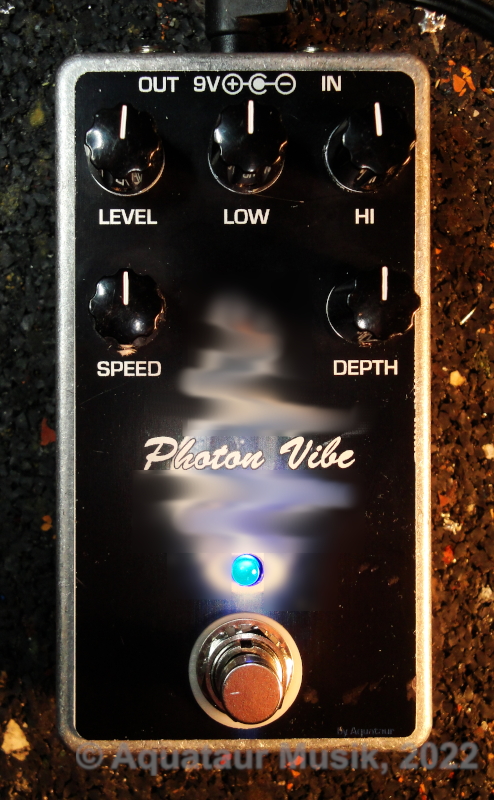
The Experience With PedalPCB´s Photon
Vibe A Lovepedal Vibronaut Clone - Setup Procedure And Customization last update: Oct. 4, 2024 Copyright 2020-25 by
H. Gragger. All Rights Reserved. All information
provided herein is destined for educational and
D.I.Y. purposes only. Commercial re-sale,
distribution or usage of artwork without explicit
written permission of the author is strictly
prohibited. The original units with their
associated trade-names are subject to the
copyright of the individual copyright owner. The
Author is by no means affiliated with any of those
companies. References to trade names are made for
educational purposes only. By reading the
information provided here you agree to the Terms
of
Use. The working language
is kept in English as an aid. Read here
why.
|
|||||
| MAIN PAGE>MUSIC STUFF>PHOTON_VIBE
Index Introduction
Unfortunately there is no hint anywhere as to how to do this. I conclude that this kit is an exact clone of the Lovepedal unit. They will surely ship their unit set up properly, in which case there is no reason to publish an exact set-up procedure. The kit maker will thus very likely not have access to this information, nor will they have the time to find out. The set-up
procedure described in the following you will
get the Photon Vibe working over its whole speed range
and produce a Univibe tone as true as it
gets.
Obviously, in order to cram the originally clumsy unit into a modern stomp box format some things had to be changed and features deemed unnecessary had to be dropped. The kit, as it comes, appears very refined and does not need any major modifications. The only improvement I would recommend is a very simple tweak of the front panel LED´s circuit in order to make the visual feedback of the low frequent oscillator (hereafter: LFO) speed more pronounced. This change is quickly done, cheap and non-invasive. To make it clear, units like that are very old technology that reflect the technical restrictions of the time being. Many modern adaptations have some of those flaws ironed out, but they will inevitably sound - modern.The methods applied here can be applied to any similar unit of course. I hope the following will be of advantage. Before you make any changes, it helps to understand what the corner points are. PedalPCB´s Photon Vibe is a clone of an original Univibe to a high degree. The LFO is, exactly like the original, comprised of discrete transistors, but the phase shifting stages are implemented by operational amplifiers (hereafter: OPAs). There is no improvement to be gained by staying discrete what so ever. Original supply voltages have been approximated by using a charge pump. The LFO is thus really identical. It is an optical unit using a filament lamp and light dependent resistors (hereafter: LDR´s) exactly like the original. Beyond that, they have even spent extra trim pots to hone in for perfect tone unlike the vintage forefathers (a curse as some may come to think).
For achieving a Hendrix-style tone in a bedroom environment, the generally agreed upon opinion is to place the unit before any high gain units (see for example discussion at above link). Remember we don´t have a true Hendrix-like signal chain. The downside of this is, although the unit does not appear overly noisy per se, that residual hiss gets amplified alongside. This is particularly obnoxious since it is the first effect in the queue, but tone indeed is most Jimi-like this way. This phenomenon is not limited to the Photon Vibe, it happens with other effects too. I tried R.O.G.'s TriVibe, which ends up not any quieter overall.It uses TL072 OPAs, but similar contemporary units[1][2] use NE5532 probably for the very reason of keeping noise down. I do not recommend NE5532 in this position, since they draw a lot of supply current which might push the charge pump to its limits. I have tried LM833 (drawing a comparable supply current with with one third of the noise figure), but it was not feeling too well there despite adding ceramic rail bypass caps. So the TL072 OPAs have to stay. The Photon Vibe has, unlike the original, no vibrato mode selectable, but this may be added easily by basically cutting the dry signal. That said, the vibrato mode appears pretty "special" to a point of being useless, which is probably why it has been dropped. (You can try it out during the setup procedure). The LFO, as it does in the original Univibe, has as some compensation built into to counteract the inability of the bulb to follow higher frequencies, by increasing the lamp drive with frequency. In other words, the effect depth increases potentially with higher speed settings. Due to this peculiarity the effect depth will appear exaggerated on higher speed settings. Use the depth control to compensate for this. Although I have never played through a vintage unit, I have reasons to believe that this is a property innate to all filament lamp units. (LED driven units will not suffer from this, but will create problems of their own). On the contrary, if you optimize tone for higher speed ranges (or don´t care when adjusting), low LFO speeds most likely won´t work, as many people have complained consequently. The original unit had no full bypass mode (as none of those units of yesteryear due to the non-availability of decent 3p2t footswitches), but the clone has of course. I noticed that upon powering up, the bypass switch seems to pop a lot, but this effect disappears after a short time.Note that the filament lamp is permanently on, despite the front panel LED suggesting being off (during bypass mode). This could be remedied by tying the emitter side of Q3 via R27 to the pin on the footswitch that activates the LED. You thus may want to remove power during prolonged periods of non-usage. Back To Index Before you start, I recommend improving the LED indicator on the front panel. We can put this to good use in the setup process lateron. The LED is meant to provide a visual clue as to what the LFO is doing. The original unit did not have such a visual user feedback, and it was a self-evident improvement to add this feature. Unfortunately, the implementation chosen does not work well (linking the LED directly to the bulb), since a LED does not vary brightness (linearly) with current the way a light bulb does. The result is that you will barely see the LED fluctuate during operation. A larger resistor does not help, it just shifts overall LED brightness into darker ranges. We will need to operate the LED close to its knee of turn-on (or, if you wish, to cut-off), and this can be achieved with a Zener diode in series. I used a 10V 1/4W specimen successfully with a blue LED, but a 9V2 gave a smoother turn on characteristic much like the lamp itself. However on low speed settings (where swing is reduced) the display was considered subjectively superior using the 10V rating. Just insert the Zener diode where the wire between PCB board terminal "SW" goes and the footswitch contact, cathode pointing towards the PCB. Back To Index Adjustment Procedure Most people (like me when I started off) make the mistake of adjusting the trimpots with both depth and speed pots set wrong. I believe that most people just twiddle the pots until it sounds better somehow. The method described hereafter optimizes for the weakest point, which is low LFO speed, by listening. All other settings fall in place naturally. Make all adjustments in a dark environment, unless you use a shroud over the opto section. Remember the case is open when you adjust and lamp and LDR´s are exposed. Trying to adjust the LFO by optical clues alone is not feasible, because the LDR´s change at low illumination conditions is more pronounced than you may think. Adjusting effect depth and waveform symmetry TR2 (illumination center value) and TR3 (lobe balance resp. signal symmetry) are both somewhat interactive. Follow the procedure exactly and always just turn one pot. There are several workable settings, but only one will give the deepest signal at low LFO settings.
Now we attend to the mixer. TR1 mixes the pitch-shifted signal with the original signal. Near center is optimum, CCW is the original signal, CW the pitch shifted version. This is done by listening. RG.Keen says[3][4] the impedances of both signal paths be matched perfectly for the most deep effect, but I cannot find such a critical pot setting around the center range.
I have mounted the LDRs flat onto the PCB, as it is shown on the component location print, and not facing the lamp as some considered. This works flawless. I have also covered the LED´s interior side (on the other side of the PCB) with black insulation tape to eliminate all possible leakage from the LED flashing on. This procedure was inspired by R.G. Keen[4]. Thank you R.G. Customizations I initially thought this unit needs no modifications, it does its thing. That said, changed circumstances have lead me into believing that indeed something could be customized for special situations. One of these special applications is explained by Bob Gjika[5], where he uses a stalled Univibe on "vibrato" setting with the intensity (=depth) turned to minimum that goes inbetween a wah pedal and a distortion unit. He thinks Hendrix has used it this way (at least in the studio; this claim has raised some dispute in the commentaries) to make the wah signal more palatable for the fuzz by both impedance matching and ironing out the wah´s nasty peaks. It is those peaks that make the wah sweep unusable in front of a fuzz. This can indeed be the case, since maybe nobody ever looked at this before from a perspective of pure necessity. Although Gjika appears to be a sworn-in defender of staying vintage at all cost, there truly is some rationality that speaks for Univibe before dirt[6]. N.B.: I cannot overemphasize the truth that we do not know what was inside those metal cases. We have been told there was such and such circuit inside of it by people continuing to make profit from their sales, so how come we see / hear so many incongruities in the gear that was allegedly used? A simple one-transistor buffer, which was perfectly doable even back then, together with some series resistance, would no doubt have solved the impedance mismatch problem elegantly, and no better or worse than a Univibe used for buffering could do...Remember the original Univibe did not have a true bypass. They shut the lamp down by grounding the input of the bulb driver resistor (on the original called "cancel"), so all LDR´s went high impedance, effectively resulting in a series of four consecutive amplifiers with very little total phaseshift. Turning the drive all the way down will have a similar result. This works on the Photon Vibe, and indeed it processes the wah signal somehow in a benign way. At the time of writing, it is not clear to me why this is, maybe some sort of compression. But there is a snag: although the phase shift is minimal in this mode, it is there, and combined with the original signal this results in a mid-cut. The Photon Vibe is hard-wired to "chorus mode", and it is slightly mid- and bass- deficient overall. Bob Gjika on the contrary used the "vibrato" mode, which is not readily accessible on the Photon Vibe. Set up this way the Photon Vibe indeed functions as a buffer. Tone change is absolutely minimal, but some dynamics shaping happens nonetheless that helps to restore the wah sweep in front of a fuzz. Again, if it was only for the buffering aspect with some series resistance, this can be solved more elegantly and with much less ado , but the Photon Vibe does something which helps the fuzz, which I cannot currently pin down.As I stated earlier, "vibrato" mode is pretty special and won´t be the to-go setting for the majority of us. That´s why they left it away. However, it still lingers there. The original unit has two 100K resistors to mix clean and phase shifted signals together 1:1. The "vibrato switch" practically suppressed the untampered part. It is pretty simple to enforce vibrato mode by shorting that branch (capacitively) to ground. This is most easily accomplished with an additional toggle switch. There is a slight volume step introduced by that action between bypassed and non-bypassed mode. Now this mod(e) would not be worth the mention for our purposes unless we shut the oscillator down. Canceling the oscillator with the original method by shorting Q3´s base to ground does not work, since the LDR´s go completely hi-Z after some seconds of total eclipse, in which case all OPA´s lose their mid-supply reference, after which the unit fades silent eventually. So different to the transistor based original the OPA based phase shifting filters' LDRs need to maintain some minute conductivity by leaving the lamp turned on somewhat. A 27 kOhm resistor to ground accomplishes that. Interestingly, by fortunate circumstances the LED drive is inverted, meaning when the bulb is on, the LED is off. In the "cancel" state it thus is fully on permanently. Although this is what the original "bypass" state was comprised of, we have not changed our true bypass wiring, so everything is genuinely on true bypass by activation of the footswitch. Ideally, if one wished, for a Hendrix setup and performance selected switching between buffered / vibe a second footswitch could be installed. A word on the Photon Vibe's input impedance: this is pretty low with 68 kOhm. As outlined by R.G. Keen[3], the resistor values there (particularly the 47 kOhm resistor) are chosen to mix two alleged instruments - which nobody does or probably ever did. But this was customary back then. Replacing the 47 kOhm to ground resistor by say, 1 MOhm would immediately increase the input resistance by a magnitude. Unfortunately the Photon Vibe has an additional passive bass blend circuit on the input which was not part of the original design, and changing the input resistor throws all time constants to hell. The two series caps and possibly the bass blend rheostat would need to be revisited. 2024 Edit: I have just recently found a useful improvement[7] (a real improvenent) on PedalPCB forum. This is a description of a stereo unit the guy made out of two Photon Vibes, along with the mods he recommends to fix some genuine design flaws.
I do not
know about the other mods he recommends, but the
ones listed improve the situation by a mile. I
always had complained about the latter effect,
and this fixes it. Again, plan it beforehand... Note that
this changes the voltage the LED sees. With
settings that low and the earlier above
recommended LED drive mod (9V Zener diode in
series), the LED goes off at very low settings.
In this case, change the Zener voltage to 5.2V
and you have restored annunciation over
the full LFO range. Note also that this mod may require to re-visit the trim pots as described above. Back To Index [1] Fred Briggs, Cloning the Uni-vibe; Neovibe / Easy Vibe / Phase 45, https://revolutiondeux.blogspot.com/2012/07/cloning-uni-vibe-neovibe-easy-vibe.html [2] JC Maillet, Univibing the Phase45, http://www.lynx.net/~jc/pedalsPhase45.html and more about modding the Univibe on this site. [3] R.G. Keen, The Technology of the Univibe, http://www.geofex.com/Article_Folders/univibe/univtech.htm [4] R.G. Keen, NeoVibe, a Univibe (tm)Workalike, http://www.geofex.com/Article_Folders/univibe/vibeupdate.pdf [5] Bob Gjika: Amp Tone Talk/Demo - Jimi Hendrix Trio Guitar Pedals - Univibe, FuzzFace, Vox Wah - Pedalboard, https://www.youtube.com/watch?app=desktop&v=viMmsxzykTA [6] Jason Wilding (Wampler Pedals): UniVibe – why it (usually) goes pre gain, https://www.wamplerpedals.com/blog/talking-about-gear/2020/01/univibe-why-it-usually-goes-pre-gain/ [7] Chuck D. Bones (PedalPCB Forum): Stereo Vibe, https://forum.pedalpcb.com/threads/stereo-vibe.4995/ Back To Index Update History
MAIN PAGE>MUSIC STUFF>PHOTON_VIBE |
|||||
| MAIN PAGE | MUSIC STUFF | IMPRESSUM (c) 2022-25 AQUATAUR Musik & Elektronik |